


Service Mode
7-8
5976053 BARCODATA 808s SP 010799
Projector Warm Up
Highlight
'Projector Warm Up'
by pushing the control disc
é
or
ê
and
press
ENTER
to select the projector warm up menu.
Select with or
then <ENTER>
<EXIT> to return.
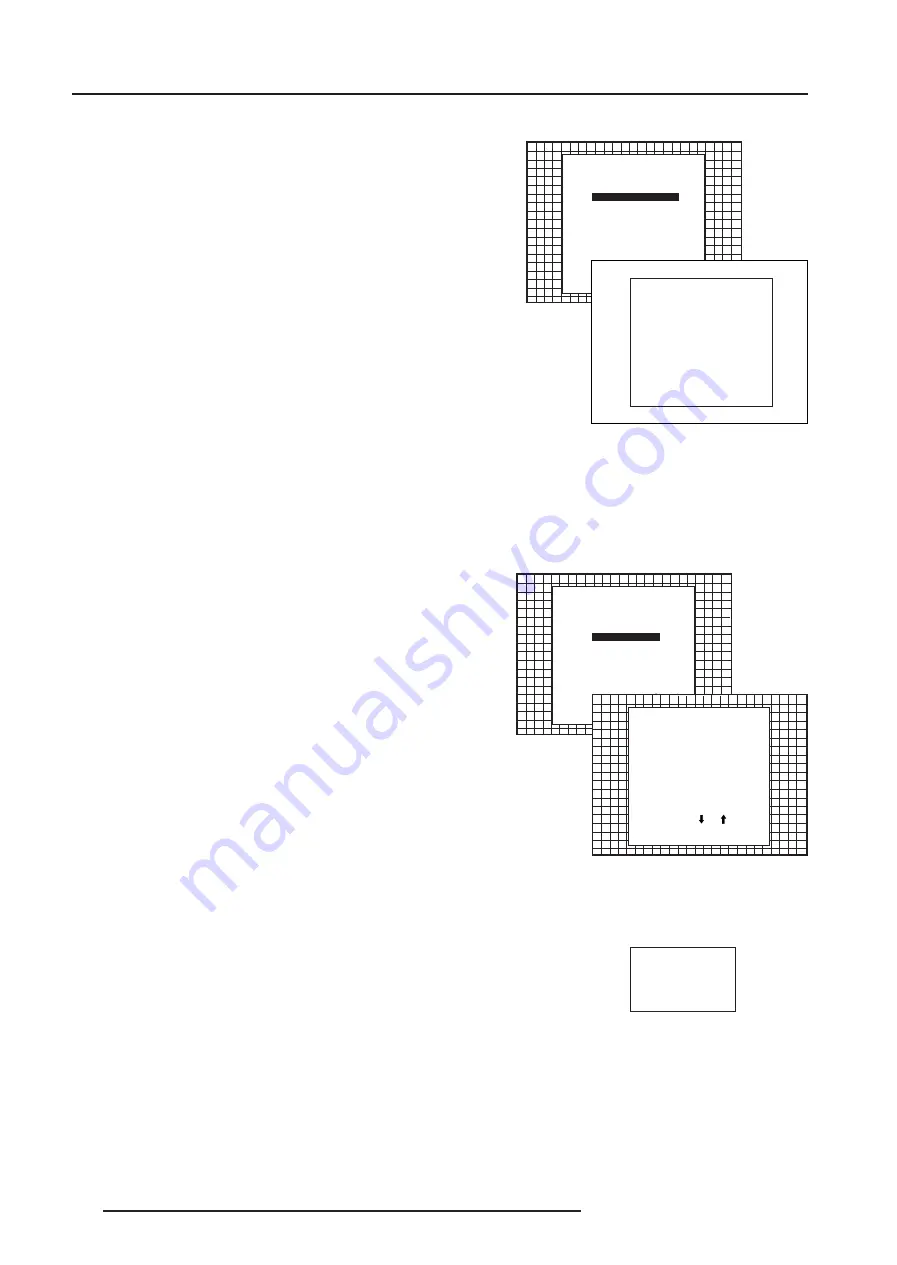
SERVICE MODE
G2 ADJUSTMENT
GAMMA CORRECTIONS
CRT RUN IN CYCLE
PROJECTOR WARM UP
CRT DRIVE MODE
MORE...
PROJECTOR WARM UP
OPTION : ON
A FULL WHITE PATTERN
WILL BE GENERATED FOR
20 MINUTES AT POWER UP
AFTER THIS PROCEDURE
THE PROJECTOR IS READY
TO PERFORM IN OPTIMUM
CONDITION
TOGGLE OPTION ON OR OFF
with <ENTER>
<EXIT> to return
The ON/OFF option can be toggled with the
ENTER
key.
When in the ON position (and the CRT run in cycle is OFF), the projector
can start up with a warm up period of 20 minutes. During the start
up a warm up menu will displayed. This menu offers the possibility
to skip the warm up periode anyway by pressing the EXIT key and
offers the possibility to adjust the horizontal and vertical amplitude of
the this white image with the control disc. During this warm up period,
a full white image is shifted on the CRT faceplate to avoid a burn in.
Every 30 seconds a text box will be displayed on another place on
the screen with the remaining time to go.
When EXIT is pressed during this warm up periode, the warm up menu
will be redisplayed with the remaining time indication. Press another
time EXIT to interrupt the warm up cycle.
When the warm up option is OFF, when switching on the the
projector, it starts immediately with the projection of the selected
source.
CRT Drive Mode
The projector CRT's can be driven with the normal current (normal
mode), a lower current (economic mode) or with a higher current
(boost mode).
To change the drive mode, highlight 'CRT drive mode' by pushing the
control disc
é
or
ê
and press ENTER to display the CRT drive mode
menu.
To change the boost mode, push the disc
é
or
ê
to select a display
mode and press ENTER to select.
The following modes are available :
- Normal
- Economic : Lower drive current to the CRT's, the lifetime of the
CRT's will enlarge but the light output will reduce.
- Tempory boost : Higher drive current to the CRT's, the lifetime of the
CRT's will shorten but the light output will be higher. This situation
is tempory, when restarting the projector, the drive mode is auto-
matically set to normal.
- Permanent boost : Higher drive current to the CRT's, the lifetime of
the CRT's will shorten but the light output will be higher. This setting
will be saved in the EEPROM. When restarting the projector, it will
start up in boost mode.
A warning, permanent BOOST mode in use, will be displayed to inform
the user.
When text is on, this warning will be repeated every time a new
source is selected.
Select with or
then <ENTER>
<EXIT> to return.
SERVICE MODE
CRT DRIVE MODE
NORMAL
ECONOMIC
TEMPORARY BOOST
PERMANENT BOOST
WARNING : permanent
boost mode reduces the
lifetime
of the CRT's !
Select with or
then <ENTER>
<EXIT> to return.
WARNING
PERMANENT
BOOST MODE
IN USE !
G2 ADJUSTMENT
GAMMA CORRECTIONS
CRT RUN IN CYCLE
PROJECTOR WARM UP
CRT DRIVE MODE
MORE...


