background image

Service Mode

7-6

5976053 BARCODATA 808s SP 010799

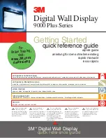
Dynamic Astigmatism (spot shape adjustment)

The spot shape adjustments correct the spot shape in 8 different

areas on the screen for all three colors separately.

The spot shape is adjusted according to the axial axises and the

diagonal axises when using the control disc on the RCU.

These adjustments have to be done on a dot pattern (e.g. the internally

generated pattern) with standard line frequency (15 kHz).  The

adjustment values are stored in the EEPROM and remain the same for

all frequencies.

Spot shapes 

before dynamic 

astigmatism correction

Spot shapes 

after dynamic 

astigmatism correction

Diagonal 

astigmatism correction

(use the      and       

arrow key)

Axial

astigmatism correction

(use the          and       

arrow key)

Follow the next procedure :

Highlight 'Dyn. Astigmatism' by pushing the control disc up or down

and press 

ENTER

 to select.

EXIT

 returns to the path selection main menu.

Select the source type, selected source or genlock pattern, by

highlighting the color for which the spot shape has to be corrected

and press 

ENTER

.

e.g. when selecting RED under 'on genlocked pattern', the projector

switches to a genlocked pattern.

Select with       or

then <ENTER>

<EXIT> to return.

SERVICE MODE

IDENTIFICATION

COPY A BLOCK

DELTE A BLOCK

DELETE ALL BLOCKS

CHANGE PASSWORD

CHANGE LANGUAGE

RUN TIME

SET TO MIDPOSITION

CONVERGENCE MID

DYNAMIC ASTIGMATISM

MORE...

DYNAMIC ASTIGMATISM

ON SELECTED SOURCE

RED

GREEN

BLUE

ON GENLOCKED PATTERN

RED

GREEN

BLUE

Select pattern or color

with       or

then <ENTER>

<EXIT> to return.

Press ENTER to continue adjustment.

Increase the contrast level using the Contrast Control to near

maximum. Using that "+" Sharpness Key, defocus the image until the

dots are large and easily visible. Press ENTER to continue to SEL.

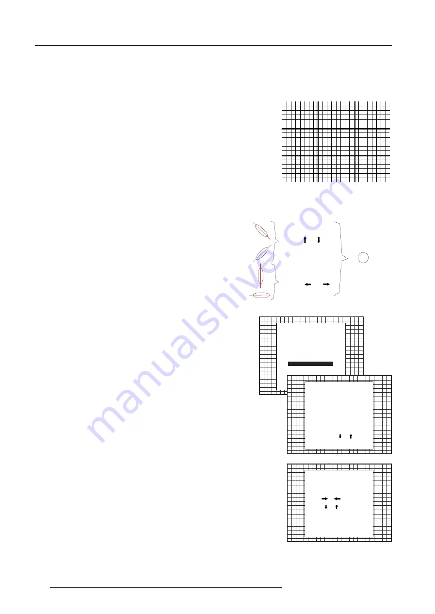
SEL : select the adjustment area on the screen where the spot shape

has to be corrected.

DYNAMIC ASTIGMATISM

First adjust the defocusing

of the image.

SEL : select area using arrow

keys

ADJ : adjust axial astigmatism

using

or         , diagonal

astigmatism using

or

Toggle between SEL and ADJ

with  <ENTER>

<ENTER> to continue

<EXIT> to return.

Use the control disc to select one of the 8 areas.  Press ENTER to

continue to ADJ.

ADJ : adjust the spot shape in the axial or diagonal direction when

using the arrow keys for the selected area.  Adjust until the spot

shape is circular.

Use the control disc 

é

 or 

ê

  for the diagonal astigmatism adjustment

and the control disc 

è

 or 

ç

  for the axial astigmatism adjustment.

Press ENTER to continue selecting a new area.

The adjustment direction (axial or diagonal) and adjustment value are

given in a text box on the screen.  When all areas are adjusted, press

EXIT to return to the service main menu.

Summary of Contents for R9002260

Page 1: ...R9002260 R9002269 OWNER S MANUAL DATA 808s SP...

Page 2: ...BARCO PROJECTION SYSTEMS Date 010799 Art No R5976053 R9002260 R9002269 OWNER S MANUAL DATA 808s SP Revision 00...

Page 3: ...ed by BARCO NV July 1999 All rights reserved Trademarks are the rights of their respective owners Printed in Belgium BARCOn v ProjectionSystems Noordlaan5 B 8520Kuurne Belgium Tel 32 56 368211 Fax 32...

Page 4: ...th Tri level sync to port 4 5 3 5 Connecting a computer to the projector 3 6 Peripheral equipment 3 6 Connecting a RCVDS 05 switcher to the projector 3 6 Connecting a VS05 switcher to the projector 3...

Page 5: ...rgence Adjustment 6 17 SERVICEMODE 7 1 Starting up the Service mode 7 1 Overview flowchart Service mode 7 1 Identification 7 2 Copy a block 7 2 Deletion of blocks 7 3 Deleting block by block 7 3 Delet...

Page 6: ...place your obsolete outlet Do not defeat the purpose of the grounding type plug WARNING FOR THE CUSTOMERS THIS APPARATUS MUST BE GROUNDED EARTHED via the supplied 3 conductor AC power cable If the sup...

Page 7: ...ti reflective coating therefore avoid touching the lens To remove dust on the lens use a soft dry cloth Do not use a damp cloth detergent solution or thinner On repacking Save the original shipping ca...

Page 8: ...ideo 2x loop through BNC connector Allows a video tape recorder video camera color receiver monitor etc having video line output to be connected to the projector 9 75 ohm Termination Switch forVideo s...

Page 9: ...emotecomputercontrolanddatacommunication CONTROL PANEL TERMINOLOGY a Gaining access to the keyboard The local keypath is mounted on the top plate of the electronic box b RCU control panel This remote...

Page 10: ...ed key to enter the address of the projector between 0 and 9 Press the address key followed by pressing one digit button between 0 and 9 4 STBY Stand by button To initiate remote power up operation To...

Page 11: ...he adjustment mode or to confirm an adjustment or selection in the adjustment mode 13 EXIT To leave the adjustment mode or to scroll upwards when in the adjustment mode 14 Control disc To make menu se...

Page 12: ...technician If you want to change this start up mode call a qualified technician Stand by indication lamp projector mode No light up projector switched off Green color projector in Operational mode Red...

Page 13: ...1 Comp Video 1 2 S Video1 Comp Video 2 3 RGB2 3 4 5 RGB2 4 or 5 4 5 Componentvideo3 6 4 5 RGB with Tri level sync4 7 4 5 Componentvideo withTri levelsync5 8 1 Input signal Y C luma chroma 2 Input sig...

Page 14: ...minancesignal Y 1Vpp 3dB Pin4 chrominancesignal C 300mVpp 3dB Forvideo Pin1 earth ground video Pin2 notconnected Pin3 videosignal Pin4 notconnected 21 2 POWER MAINS S HUL S K HU DOV 5 RPS 6 Q F 9 6 Q...

Page 15: ...HT 6 HH L Q VWDOOD WLR Q L Q V WUXF WLR Q V EHI RU H FR QQ HFW L Q J W R WK H VXS SO 9 R LU O D QR W L FH G L Q VW D O O DW L RQ DYD QW GH U DFF RUG HU D X UpV HDX 9 P S 6 9 2 2 2 1 2 KP 9 2 JUHHQ RS...

Page 16: ...XVH XQG HV LU HG RS HU DW L R Q 5 6 1 5 6 2 8 7 5 5 0 2 7 56 1 56 287 5 5 027 PORT 4 5 PORT 3 COMM PORT PORT 2 PORT 1 PROJECTOR MODE POWER MAINS 9 5 79 SOD HU RPSRVLWH YLGHR XGLR 2XW 21 2 POWER MAINS...

Page 17: ...lities address range from 0 to 255 b data communications sending data to the projector or copying the data from the projector to a hard memory device PERIPHERAL EQUIPMENT Connecting a RCVDS 05 switche...

Page 18: ...battery installation procedure Remove the battery cover on the backside of the RCU by pushing the indicated handle a little to the bottom of the RCU Lift up the top side of the cover at the same time...

Page 19: ...H FWL Q J W R W KH V X S SO 9 RLU OD Q R WL F H G LQ V WD OOD WLR Q D Y D QW GH UD FF RUGHU D X Up VH D X 9 P S 6 9 2 2 21 2K P 9 2 J UH H Q R S H UD W LR Q UH G V W D QG E PORT2 PORT 1 2 21 2KP PROJ...

Page 20: ...RGsB or RGBS RG3sB or RGB3S When a valid and available source is selected there will be informa tion displayed on the screen about that source if Text is on This information includes Source number Hor...

Page 21: ...trol is effective only when using the NTSC 4 43 or NTSC 3 58 system A bar scale gives a visual indication on the screen of the current tint setting while pressing the or buttons RCU If the bar scale i...

Page 22: ...tor will be warned to call a qualified technician to perform the installation procedure see example of projected warning on the next page GUIDED Guided should be selected if the user intends to perfor...

Page 23: ...gits Enter the digits with the numeric keys on the RCU Example 2 3 1 9 For each digit entered a X appears on the screen under the displayed text enter password When your password is correct you gain a...

Page 24: ...STMENT MODE Select a path from below GUIDED RANDOM ACCESS SERVICE IRIS Source 01 Select with or then ENTER EXIT to return ENTER continues to Setup Pattern Selection EXIT returns to Operational mode RA...

Page 25: ...TOP VLINEARITY COARSEADJUSTMENT From next page From next page SETUPPATTERNSELECTION FOCUSING BLUE GREEN RED BLUE GREEN RED REDANDBLUE BLUEANDGREEN REDANDGREEN COLORSELECT ORBITING CONTRASTMODULATION...

Page 26: ...ated for an external source connected to one of the inputs and the Genlocked Pattern is selected Internal Cross Hatch Pattern The Internal pattern menu will be displayed if the internal cross hatch pa...

Page 27: ...lect custom R B cut off with the control disc and press enter to start the adjustment Push the control disc or to adjust the red cut off and push the control disc or to adjust the blue cut off Select...

Page 28: ...IGH FREQUENCY ClampTuning Highlight CLAMP TUNING by pushing the control disc or and press ENTER to toggle between NORMAL and RESTORATION Select Normal for all standard sources and all sources with a b...

Page 29: ...ress ENTER to toggle between ON active and OFF non active EXIT will return to the random access selection menu Select with or ENTER to accept EXIT to return PICTURE TUNING COLOR BALANCE SYNC FAST PORT...

Page 30: ...the left or to the right to adjust the top focusing Adjust until the upper part of the image is sharp ENTER to return to the Green Focusing menu Bottom image focusing The same procedure has to be repe...

Page 31: ...ft Right Corrections Left Side Corrections Top Bottom Corrections Horizontal Size Vertical Linearity Vertical Size Blanking The convergence corrections are disabled during geometry correc tions The bl...

Page 32: ...LEFT RIGHT E W LEFT SIDE CORRECTION TOP BOTTOM N S H SIZE V LINEARITY V SIZE BLANKING ENTER will select green raster shift adjustment EXIT returns to random access adjustment mode menu Warning In orde...

Page 33: ...E SKEW SIDE BOW SIDE KEYSTONE SEAGULL CORRECTION Warning Use this correction to adjust the right side of the image The warning Use this correction to adjust the right side of the image appears on the...

Page 34: ...ion insure that the side bow and keystone adjustments are done prior to these fine adjustments The following adjustments can be executed Left keystone Left bow Push the control disc or to highlight LE...

Page 35: ...the vertical lines are straight To enter an alignment push the control disc or to highlight a function and press ENTER to activate this function Press EXIT to return TOP BOTTOM Select with or then EN...

Page 36: ...S H SIZE V LINEARITY V SIZE BLANKING TOP BOTTOM N S H CENTERLINE BOW H CENTERLINE SKEW TOP KEYSTONE TOP BOW BOTTOM KEYSTONE BOTTOM BOW SEAGULL CORRECTION Horizontal Size Adjustment Pushthecontroldisc...

Page 37: ...70 Vertical Size Adjustment Push the control disc forward or backward to highlight V SIZE on the Geometry menu and then press ENTER ENTER will select vertical size adjustment EXIT returns to random ac...

Page 38: ...BLANKING Select with or then ENTER EXIT to return BLANKING TOP BOTTOM LEFT RIGHT The following blanking corrections are possible Top blanking Bottom blanking Left blanking Right blanking Therefore If...

Page 39: ...ms are possible Horizontal sides adjust the vertical lines within a certain area on both sides without influencing the lines on the middle of the image Vertical corners adjust the horizontal lines in...

Page 40: ...sc to make horizontal or vertical convergence adjustments in the selected zone and then press ENTER to move the box to another zone or EXIT to return to the Convergence menu ENTER toggles arrow keys b...

Page 41: ...o the second menu or vice versa push the control disc forward or backward to select more Select with or then ENTER EXIT to return SERVICE MODE IDENTIFICATION COPY A BLOCK DELTE A BLOCK DELETE ALL BLOC...

Page 42: ...e control disc and press ENTER ENTER will select the highlighted item To copy the settings of a closed block to the block you are working on active block use the control disc to select a block All exi...

Page 43: ...block nr 1 DELETE BLOCK The selected block will be deleted ENTER to confirm EXIT to cancel Push the control disc or to select the desired adjustment block Press ENTER to delete the selected adjustmen...

Page 44: ...WORD Enter new password 0 0 0 0 Password will be reprogrammed as xxxx ENTER to confirm EXIT to cancel CHANGE PASSWORD IDENTIFICATION COPY A BLOCK DELTE A BLOCK DELETE ALL BLOCKS CHANGE PASSWORD CHANGE...

Page 45: ...hen undo is pressed all settings are reset to the previous settings Convergence Mid Item is password protected Highlight convergence mid with the control disc and press ENTER to set all convergence se...

Page 46: ...OCK DELTE A BLOCK DELETE ALL BLOCKS CHANGE PASSWORD CHANGE LANGUAGE RUN TIME SET TO MIDPOSITION CONVERGENCE MID DYNAMIC ASTIGMATISM MORE DYNAMIC ASTIGMATISM ON SELECTED SOURCE RED GREEN BLUE ON GENLOC...

Page 47: ...eturn SERVICE MODE WARNING RISK OF INCORRECT ADJUSTMENT OF THE PROJECTOR THE GAMMA CORRECTIONS ARE FACTORY ADJUSTED USING AN ACTAS COLOUR ANALYSER THEREFORE ONLY QUALIFIED INSTALLTION OR SERVICE PERSO...

Page 48: ...witching on the the projector it starts immediately with the projection of the selected source CRT Drive Mode The projector CRT s can be driven with the normal current normal mode a lower current econ...

Page 49: ...lecting an in put slot of an RCVDS where the input board is missing When selecting a new source information about this source will be displayed on the screen Source number horizontal and vertical freq...

Page 50: ...s sage on which the user has to answer FAILURE invalid RWI soft version Wrong software version in your projector Call for technical sup port FAILURE I2 C error addr 7FH3 Hardware failure Call a quali...

Page 51: ...sfering and receiving data of projector settings Remote Control Simulation Advantage address range 0 to 255 Adjustment Data Where can it be located when a IBM PC or compatible or MAC or Workstation is...

Page 52: ...unication cables BARCO provides several cables to connect peripheral equipment to the projector a D9 D9 communication cable To connect an IBM PC or compatible to the projector To connect a RCVDS05 to...

Page 53: ...e block header A ADJUSTMENT BLOCKS AND SOURCE NUMBERS 90 99 Source numbers 90 99 Source numbers 90 99 do not correspond to physical inputs to the projector or RCVDS They are used to assign an addition...

Reviews: