background image

6-1

Controlling

5976052 BARCOREALITY 9300 070999

6

Ceiling

Screen

IR sensor

RCU

R

G

B

V

R

G

B

H / C 

V

On

98

 279

10

R

G

B

H / C 

V

H

9,'(2,1387

9,'(2

69,'(2

RS 232 IN

REMOTE

PROJECTOR MODE :

GREEN - OPERATION

RED - STANDBY

COMMUNICATION PORT

(800-PERIPHERALS)

RS23 2 OUT

IR-ACKNOWLEDGED

IR-RECEIVED

DIAGNOSTICS

CODE

IR-RECEIVER

9

$

+]

0 I

T h is  d ev ic e  c o m p l ies  w i th  P a rt  15  o f  the  F C C  r u les .   O p e r a tio n

is   s u b je c t   to   f o llo w in g   t w o  c on d itio n s   :

( 1)  T h is  d e v ic e  m a y  n o t c au s e  h ar m fu l i n te rf er e n c e

( 2)   T h is   d e v ic e   m u s t  ac c e p t   a ny   in t er fe r en c e   r ec eiv e d

in c lu d in g    in te rf er e nc e  t ha t  m ay  c a u s e  u n d e s ire d   op e ra tio n 

RCU

SDI IN

SDI OUT

XLR

CONTROLLING

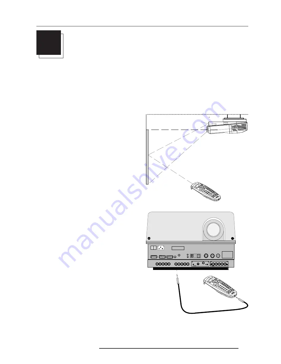
The projector can be controlled with

a. The RCU

b. The hardwired RCU via mini jack (cable is not included)

c. The hardwired RCU via XLR plug (cable not included)

c. The local keypad.

Controlling the projector with the RCU and the hardwired RCU is equal.

How to Use the RCU?

a) Point the front of the RCU to the reflective screen surface.

b) RCU used in a hardwired configuration.

Plug one end of the remote cable in the connector on the bottom of

the RCU and the second side in the connector in the front panel of

the projector labelled 'REMOTE'.

Summary of Contents for R9001560

Page 1: ...OWNER S MANUAL REALITY 9300 DLC R9001560 R9001569...

Page 2: ...uses and can radiate radio frequency energy and if not installed and used in accordance with the instruction manual may cause harmful interference to radio communications Operation of this equipment...

Page 3: ...BARCO PROJECTION SYSTEMS Date 070999 OWNER S MANUAL REALITY 9300 DLC R9001560 R9001569 Art No R5976052...

Page 4: ...CONTROLLING 6 1 How to use the RCU 6 1 Projector address 6 1 How to display a projector address 6 2 How to program an address into the RCU 6 2 Picture controls with direct access 6 2 START UP OF THE...

Page 5: ...s with the removed bolts and turn in then mount both plastic parts to finish the feet Warning To prevent overheating of the projector as table mounted always remove the wooden board and turn in the 3...

Page 6: ...he battery cover on the backside by pushing the handle a little towards the bottom of the RCU 2 Lift up the top side of the cover at the same time 3 Push on the side of the battery towards the side 4...

Page 7: ...rtant As a general rule darken the room to the point where there is just sufficient light to read or write comfortably Spot lighting is desirable for illuminating small areas so that interference with...

Page 8: ...e projector as described in the manual Inputs and computer video format input compatibility Some examples VIDEOandS VIDEO COMPONENTVIDEO RGB ANALOG with STANDARD SYNC SYNC ON GREEN or SEPARATESYNC RGB...

Page 9: ...put autoranging from 200 to 240 Vac Identification plate name serial number art number Voltage identification plate name art number SDIIN SDIOUT option Serialdigitalinputandlooptrough output 2 x BNC t...

Page 10: ...er the address of the projector between 0 and 9 Press the recessed address key with a pencil followed by pressing one digit button between 0 and 9 4 Selection key no function 5 PAUSE tostopprojectionf...

Page 11: ...cal keypad to make menu selections when in the adjustment mode or to zoom focus when the direct access is active Comparision between the cursor keys and the use of the and keys on the local keypad RCU...

Page 12: ...3 4 Location and Functions of Control 5976052 BARCOREALITY 9300 070999...

Page 13: ...ct The configuration menu will be displayed ENTER displays the Configuration menu EXIT returns to the path selection menu ADJUST returns to operational mode The actual selected configuration will be h...

Page 14: ...torted picture from a non standard projection position The shift of the lensholder is not determined by the lens used but depends on the screen width Can be used with all available lenses Can be used...

Page 15: ...US E R S23 2 IN R EM OT E IR R E CE IV ER F10A H 250V PR OJEC T ORM OD E G RE EN O PER AT ION R E D STAN D BY CO M M UNICA TIO NPO RT 8 00 P ER IP HE RA L S 9 Insert a wrench 13 mm into the slot on t...

Page 16: ...Installation Set Up 4 4 5976052 BARCOREALITY 9300 070999...

Page 17: ...ic e m u st a c ce p t a n y i n te r fe r e n c e r e c e ive d i n cl ud in g in te r fe re n c e t h a t m a y c a u s e u n d e s ir e d o p e r a tio n R S232IN CO MM U NIC ATIO NPOR T 800 PER I...

Page 18: ...nput module insertion into the projector Power down the projector and disconnect the power cord from the wall outlet Remove the dummy plate covering the chosen input slot by turning out both screws Sl...

Page 19: ...Green 0 7 Vpp 3 dB Vert sync 1 Vpp to 4 Vpp 3 dB Hor sync Composite sync 1 Vpp to 4 Vpp 3 dB All input signals are always 75 ohm terminated even in the not selected mode Slot 1 selection Key in 1 on t...

Page 20: ...ct these 5 cables to this fixed 5 input slot slot2 of the projector All sources of the RCVDS can now be accepted by the projector Slot 2 selection Key in 2 on the RCU or the local keypad Selection of...

Page 21: ...luminance 1 0 Vpp 3 dB 4 chrominance 282 mVpp 3 dB Input selection Key in the corresponding slot number on the RCU or the local keypad Depending on the priority setting in the Input slots menu Video...

Page 22: ...have to be connected to the projector See slot 1 for interfaces to be applied RGBS RGsB analog 5 x BNC Red 0 7 Vpp 3 dB Blue 0 7 Vpp 3 dB Green 0 7 Vpp 3 dB 1 Vpp 3 dB if sync on green Vert sync 1 Vp...

Page 23: ...ate sync is composite sync or horizontal and vertical sync RGB SOG sync on green Component Input Module Connect your component signals Y luma R Y and B Y e g a professional VCR to the Component input...

Page 24: ...strap yes non floating strap no floating S J6 strap yes non floating strap no floating Factory preset strap yes non floating input Sync selection J8 strap no separate sync strap yes sync on Y J9 stra...

Page 25: ...non floating strap no floating V J7 strap yes non floating strap no floating Factory preset strap yes non floating input Sync selection J8 separate sync or sync on green Factory preset separate sync S...

Page 26: ...tor In addition the audio signal proper to the source can be switched to an audio amplifier Order number R9827890 For more information about the use of the VS05 consult the VS05 owner s manual BARCO o...

Page 27: ...n te rf er e n c e 2 T h is d e vice m u st ac ce p t a ny in t er fe r en ce r ec eiv e d in clu d in g in te rf er e nc e t ha t m ay ca u s e u n d e s ire d op e ra tio n RCU SDI IN SDI OUT XLR C...

Page 28: ...between 0 and 255 Note A projector will respond to a RCU set to an address of 0 regardless of what address is set in the projector itself c Using the RCU Before using the RCU its is necessary to enter...

Page 29: ...e bar scale and the value of the numeric indication indicate the current memorized setting for this source The bar scale changes as the control disc on the RCU is pressed or the or buttons on the loca...

Page 30: ...item When your password is wrong The error message Invalid password is displayed on the screen Press EXIT to continue and to return to the Service menu Factory programmed password 0 0 0 0 Once the pas...

Page 31: ...ce a correct file has to be installed The projector s memory contains a list of files corresponding to the most used sources When the new source corresponds with one of these files the file can be loa...

Page 32: ...d with the newly created file and the one on which the new file is based on 3 Press ENTER to confirm the new creation or EXIT to return to the load file menu Note When scrolling through the files the...

Page 33: ...ify the input source file If the value for Horizontal Total Pixels is wrong sampling mistakes small vertical bars in the projected image will be seen in the image Select Total and adjust the pixel qua...

Page 34: ...cy of the incoming source Synchronous refresh cannot be used Vertical Sync Polarity leading or trailing The vertical refresh can be synchronised with the leading sync edge or trailing sync edge Defaul...

Page 35: ...keys on the RCU 3 Press ENTER to confirm The renamed file is entered in the list of files 4 Press EXIT to return to the Copy menu selection No changes are made Delete To delete a selected file out of...

Page 36: ...ynamic color depth noise reduction input balance RANDOM ACCESS ADJUSTMENT MODE FILE SERVICE PICTURE TUNING GEOMETRY PICTURE TUNING CTI ON COLOR TEMPERATURE GAMMA DECODING EBU DYNAMIC COLOR DEPTH NOISE...

Page 37: ...r via the European EBU standard DecodingaNTSCsignalusingtheEuropeanEBUstandardmayresult in a greenish tint 1 Push the cursor key or to highlight Decoding 2 Press ENTER to toggle between EBU or IRE 3 P...

Page 38: ...m adjustment file This procedure is not so easy Attention Before starting the Input Balance function generate a signal with dominant black and white areas The default values are normally loaded when s...

Page 39: ...in a vertical direction Push the cursor key or to shift the image in a horizontal direction The default value for the shift is 0 Shifting in a vertical direction when the shift value is positive the...

Page 40: ...than the lower part of the image push the cursor key The number indication below the bar scale will be negative When the upper part of the image is smaller than the lower part of the image push the cu...

Page 41: ...same side keystone correction for all files YES ENTER to toggle EXIT to return BLANKING TOP BOTTOM LEFT RIGHT Select with or then ENTER EXIT to return Options To change the geometry options 1 Push the...

Page 42: ...select The internal system will scan the input slots and displays the result in the Input slots menu Source indication Video or S Video Video Video Video S Video RGB analog RGB SS CV separate sync is...

Page 43: ...r on be used as the reference image to converge the red and blue image The following alignments have to be done You have to adjust the green panel until the indicated lines on the screen are focused s...

Page 44: ...n Green Focusing 1 Highlight Green by pushing the cursor key or andpress ENTER 2 Adjust the projection lens until optimal focus on position 3 is obtained hint use the focusing marker lines next to the...

Page 45: ...eturn CONVERGENCE GREEN TO MIDPOSITION GREEN BLUE ON GREEN RED ON GREEN HATCH ABOUT MOCA Hatch To check the result of the convergence adjustment 1 Push the cursor key or to highlight Hatch 2 Press ENT...

Page 46: ...PURITY PAGE CHAR ALPHA NUMERIC CHARS Select with or then ENTER EXIT to return INSTALLATION INPUT SLOTS 800 PERIPHERALS CONVERGENCE CONFIGURATION OSD COLOR NO SIGNAL BLACK INTERNAL PATTERNS No Signal B...

Page 47: ...r then ENTER EXIT to return SERVICE IDENTIFICATION CHANGE PASSWORD CHANGE LANGUAGE CHANGE PROJ ADDRESS CHANGE BAUDRATE PC RESET LAMP RUNTIME LAMP RUNTINE HISTORY LAMP DRIVE MODE MORE Select with or th...

Page 48: ...h or then ENTER EXIT to return software version Proj Address to change the address of the projector see Change Projector Address in this chapter Installation possible installations Front Ceiling Front...

Page 49: ...c e iv e d in cl u d in g in t e r fe r e n ce t h a t m a y c a u se u n d e s ir e d o p e r a t io n Select with or then ENTER EXIT to return Password switch Change Password This item is password...

Page 50: ...baud rate speed can be software set 1 Push the cursor key or to highlight Change Bau rate PC 2 Press ENTER to display the Change Baudrate PC menu The following baud rates are available 230400 115200 5...

Page 51: ...ive Mode 2 Press ENTER to select 3 Push the cursor key or to highlight the desired lamp drive mode 4 Press ENTER to select BARCO logo The BARCO logo can be added to the image in overlay or on a backgr...

Page 52: ...lance 2 Press ENTER to select When Preset Input Balance is selected in the Service Mode selection menu the following warning will be displayed Preset Input Balance is reserved to qualified service per...

Page 53: ...350 EWS_50 1280 X 1024 50 000 52 350 87 948 1680 1280 1047 1024 EWS_60 1280 X 1024 60 000 63 900 107 352 1680 1280 1065 1024 EWS_60V 1280 X 1024 60 282 63 657 110 000 1728 1280 1056 1024 EWS_72 1280 X...

Page 54: ...984 48 287 64 125 1328 1024 805 768 SUNXGA70 1024 X 768 70 041 56 596 74 250 1312 1024 808 768 SUNXGA77 1024 X 768 77 069 62 040 84 375 1360 1024 805 768 SUP_MAC 1024 X 768 60 000 48 780 63 999 1312...

Page 55: ...Cleaning procedure for the other HD lens To minimize the possibility of damaging the optical coating or scratch ing exposed lens surfaces we have developed recommendations for cleaning lenses FIRST we...

Page 56: ...mulas to calculate the projector distance QHD 1 2 1 Metric PD 1 264 x SW 0 28 Inch PD 1 264 x SW 11 02 HD 2 2 1 Metric PD 2 0566 x SW 0 16 0 029 SW Inch PD 2 0566 x SW 6 299 44 95 SW HD 3 3 1 Metric P...

Page 57: ...eate a second or a third file for sources 0 to 9 1 Select the source between 0 and 9 2 Select the corresponding source number between 80 and 99 with the digit keys on the RCU 3 Enter the adjustment mo...

Page 58: ...he physical inputs 1 5 of the projector e g When slot 1 of the projector has to be selected key in source number 81 The relationship between the sources of slot 1 5 of the projector with 800 periphera...

Page 59: ...5976052 BARCOREALITY 9300 070999 3 5 8 1387 62 85 6 352 725 5 9 6 1387 6285 6 3 5 8 1387 62 85 6 352 725 5 9 6 1387 6285 6...

Reviews: