background image

Options

9-1

5975007 BARCOGRAPHICS 808s 051196

IR Receiver 800

This infrared receiver unit makes it possible to control the
BARCOGRAPHICS 808s from another room.
There is a communication line with cable between the IR receiver and
the projector or the RCVDS05.  The control information from the RCU
can now be sent to this IR receiver.
The IR receiver 800  displays the selected source on a 7-segment
display.
Order number : R9827515

Hardwired RCU.

The control signals from the RCU can be sent to the projector via a
wired connection.

9

OPTIONS

shield

conductor

Preparing your remote cable :

Use a shielded cable with a maximum length of 100 m and two mini-
jack 3.5 mm connectors (order number : R3131991).

- Peel back the vinyl covering of the cable on both sides and twist the

wire core.

- Solder a jack plug as shown in drawing above to each end of the

cable.
shield = ground
conductor = data information

When the cable is ready, plug one side in the remote control and the
other side in the connector on the rear of the projector labelled
‘remote’.

Projector Control software

The software is user-friendly and makes full use of : mouse control,
pull down menus and dialog boxes.

Two main applications are available with this software : remote
control and transfering and receiving data of projector settings.

Remote Control Simulation.  Advantage : address range 0 to 255.

Adjustment Data : where can it be located when a IBM PC (or
compatible) or MAC or Workstation is connected :

- hard memory device with files of settings.
- the contents of the local memory of the computer.
- the contents of the projector.

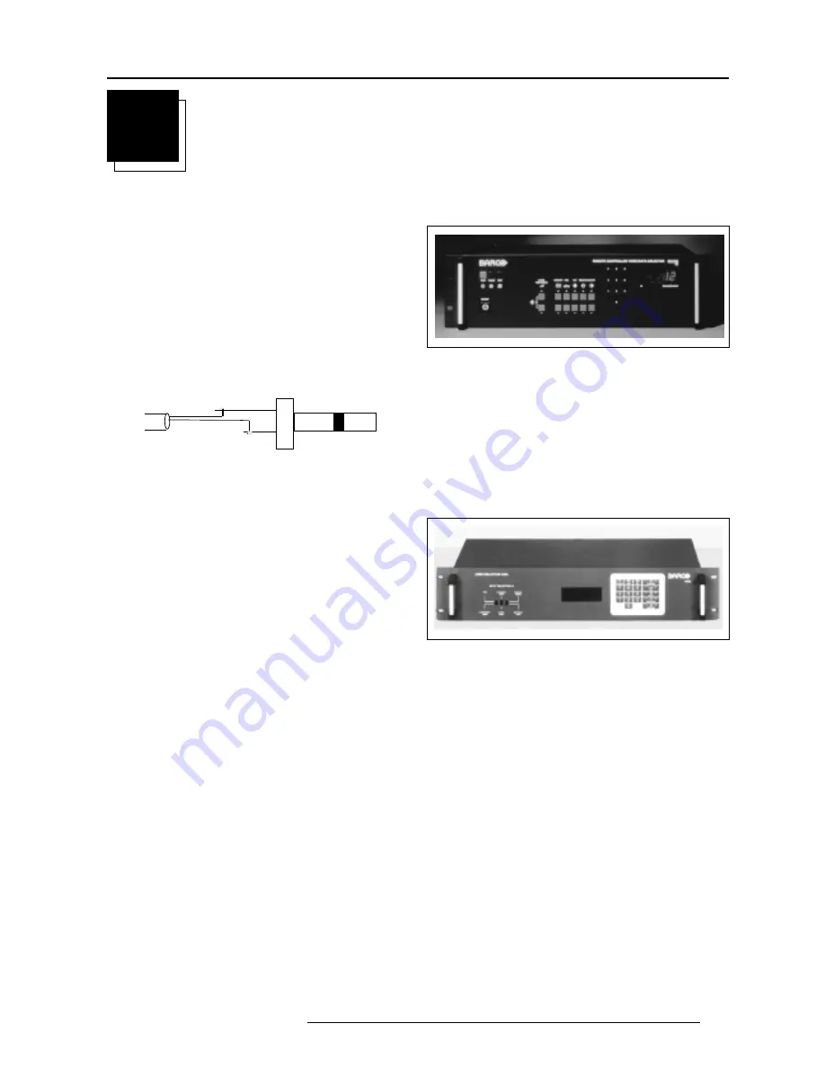
RCVDS 05 Source Selector

An optional RCVDS05 makes it possible to connect up to 20 sources
to the projector.  When RCVDS's are linked via the expansion module,
even 90 inputs can be connected to the projector.
The selected source number will be displayed on a 2 digit display and
the selected input module will be indicated with a LED on the rear.
Order Numbers RCVDS 05:

110V:

9827888
9827889

220V:

9827880
9827881

VS05 Switcher

The VS05 is a versatile Video and HDTV source selector for all
BARCO's digitally controlled large screen projectors.  It offers the
possibility to connect and switch up to 5 different Video sources, 3
different S-Video sources and 1 RGB Analog source to a BARCO
projector.  In addition,  the audio signal proper to the source, can be
switched to an audio amplifier.
Order Numbers:

110V:

9827890

220V:

9827899

IRIS/2 Auto-Convergence System

Option for R9000901 and R9000908.  Standard available on the both
other order numbers.
Easy-to-use, high precision automatic convergence system.
Convergence time : less than 2'30''
Various options on the menu offer you the optinal solution for your own
individual needs :

- Align : convergence starts from the current image situation
- Align from midposition : convergence starts from midposition
- Touch-up : convergence starts when the source switches or after

a user-defined time : alignment of static convergence almost
invisible for the audience.

Order Number: R9828270

Summary of Contents for R9000901

Page 1: ...GRAPHICS 808s R9000901 R9000908 OWNER S MANUAL...

Page 2: ...BARCO PROJECTION SYSTEMS Date 051196 Art No R5975007 GRAPHICS 808s R9000901 R9000908 OWNER S MANUAL...

Page 3: ...t notice Produced by BARCO NV November 1996 All rights reserved Trademarks are the rights of their respective owners Printed in Belgium BARCO nv Projection Systems Noordlaan 5 B 8520 Kuurne Belgium Pr...

Page 4: ...VS05 switcher to the BARCOGRAPHICS 808s 3 6 Connecting an IR Remote Receiver to the BARCOGRAPHICS 808s 3 6 Controlling 4 1 Battery installation in the RCU 4 1 How to use your RCU 4 2 Projector Addres...

Page 5: ...ck by block 7 3 Deletion of all blocks 7 3 Change password 7 4 Change Language 7 4 Run time 7 4 Set to midposition 7 5 Undo Midposition 7 5 Convergence Mid 7 5 Undo Convergence Mid position 7 5 Dynami...

Page 6: ...afety feature If you are unable to insert the plug into the outlet contact your electrician to replace your obsolete outlet Do not defeat the purpose of the grounding type plug WARNING FOR THE CUSTOME...

Page 7: ...the power cord or plug is damaged or frayed b If liquid has been spilled into the equipment c If the product has been exposed to rain or water d If the product does not operate normally when the oper...

Page 8: ...RGB output to be con nected to the projector Lineinputs signals RED GREEN BLUE COMPOSITE sync signal Tri level sync signal option 1 2 S VIDEOInput SeparatedY C luma chroma signalinputs andoutputsforh...

Page 9: ...and 9 Press the address key followed by pressing one digit button between 0 and 9 STBY stand by button to initiate remote power up operation to stop projection without main power off Pause to blank th...

Page 10: ...R9000901 must be connected to a 230 VAC power source Art No R9000908 must be connected to a 120 VAC power source If the wall outlet voltage is different call a qualified technician for power adaptatio...

Page 11: ...e displayed Please use EXIT to leave this procedure b Start up without warm up period If the EXIT key is pressed the warm up period will be skipped and the projector is immediately ready for use Warni...

Page 12: ...r or to a monitor This device complies with part 15 of the FCC rules Operation is subje ct to following two conditions 1 This devicemay not cause harmfulinter ference and 2 this dev ice must accept an...

Page 13: ...hm term 361 This device complies with part 15 of the FCC rules Operation is subje ct to following two conditions 1 This devicemay not cause harmfulinter ference and 2 this dev ice must accept any inte...

Page 14: ...e conne cting to the supply Voirla notice d installation avant de raccorderaur seau 120 230 V 7 5 Amp 50 60 Hz 75 Ohm PORT 2 75 Ohm 798 VCR HDTV player Audio amplifier This device complies with p art...

Page 15: ...nnecting a VS05 switcher to the BARCOGRAPHICS 808s The VS05 can switch up to 5 Composite Video sources 3 S Video Sources and 1 RGB analog or component Video source to the BARCOGRAPHICS 808s In additio...

Page 16: ...battery installation procedure Remove the battery cover on the backside of the RCU by pushing the indicated handle a little to the bottom of the RCU Lift up the top side of the cover at the same time...

Page 17: ...ginterferencethatmaycause undesiredoperation c RCU used in a hardwired configuration RS232 IN RS232 OUT IR REMOTE RS232 IN RS232 OUT IR REMOTE 219 Plug one end of the remote cable in the connector on...

Page 18: ...on With the digit buttons on the RCU it is possible to select input sources Video S Video RGsB or RGBS RG3sB or RGB3S When a valid and available source is selected there will be informa tion displayed...

Page 19: ...cture Adjust the color saturation using the and buttons RCU A bar scale gives a visual indication on the screen of the current color setting while pressing on the above indicated keys If the bar scale...

Page 20: ...hnician to perform the installation procedure see example of projected warning on the next page GUIDED Guided should be selected if the user intends to perform a complete alignment of the projected im...

Page 21: ...its Enter the digits with the numeric keys on the RCU Example 2 3 1 9 For each digit entered a X appears on the screen under the displayed text enter password When your password is correct you get acc...

Page 22: ...Select a path from below GUIDED RANDOM ACCESS INSTALLATION SERVICE IRIS Source 01 Select with or then ENTER EXIT to return ENTER continues to Setup Pattern Selection EXIT returns to Operational mode R...

Page 23: ...NVERGENCE H SIZE V SIZE BLANKING LEFT BOTTOM RIGHT TOP V LINEARITY GREEN ONLY BLUE ON GREEN RED ON GREEN FOCUSING BLUE GREEN RED BLUE GREEN RED RED AND BLUE BLUE AND GREEN RED AND GREEN COLOR SELECT O...

Page 24: ...ed for an external source connected to one of the inputs and the Genlocked Pattern is selected Internal Cross Hatch Pattern The Internal pattern menu will be displayed if the internal cross hatch patt...

Page 25: ...ct custom R B cut off with the control stick and press enter to start the adjustment Push the control stick forward or backward to adjust the red cut off and push the control stick to the left or to t...

Page 26: ...NCY Clamp Tuning Highlight CLAMP TUNING by pushing the control stick forward or backward and press ENTER to toggle between NORMAL and RESTORATION Select Normal for all standard sources and all sources...

Page 27: ...ON active and OFF non active EXIT will return to the random access selection menu Select with or ENTER to accept EXIT to return PICTURE TUNING COLOR BALANCE SYNC FAST PORT2 S VIDEO LINE DOUBLER ON Co...

Page 28: ...o the left or to the right to adjust the top focusing Adjust until the upper part of the image is sharp ENTER to return to the Green Focusing menu Bottom image focusing The same procedure has to be re...

Page 29: ...ft Right Corrections Left Side Corrections Top Bottom Corrections Horizontal Size Vertical Linearity Vertical Size Blanking The convergence corrections are disabled during geometry correc tions The bl...

Page 30: ...IGHT E W LEFT SIDE CORRECTION TOP BOTTOM N S H SIZE V LINEARITY V SIZE BLANKING ENTER will select green raster shift adjustment EXIT returns to random access adjustment mode menu Warning In order to e...

Page 31: ...SIDE KEYSTONE SEAGULL CORRECTION Warning Use this correction to adjust the right side of the image The warning Use this correction to adjust the right side of the image appears on the screen when sel...

Page 32: ...rrection insure that the side bow and keystone adjustments are done prior to these fine adjustments The following adjustments can be executed Left keystone Left bow Push the control stick forward or b...

Page 33: ...raight To enter an alignment push the control stick forward or backward to highlight a function and press ENTER to activate this function Press EXIT to return TOP BOTTOM Select with or then ENTER EXIT...

Page 34: ...ZE V LINEARITY V SIZE BLANKING TOP BOTTOM N S H CENTERLINE BOW H CENTERLINE SKEW TOP KEYSTONE TOP BOW BOTTOM KEYSTONE BOTTOM BOW SEAGULL CORRECTION Horizontal Size Adjustment Push the control stick fo...

Page 35: ...INEARITY 70 Vertical Size Adjustment Push the control stick forward or backward to highlight V SIZE on the Geometry menu and then press ENTER ENTER will select vertical size adjustment EXIT returns to...

Page 36: ...ng Left blanking The following blanking corrections are possible top blanking bottom blanking left blanking right blanking Therefore if the internal pattern was selected this pattern remains on the sc...

Page 37: ...NTER to display the convergence adjustment menu CONVERGENCE Select with or then ENTER EXIT to return GREEN ONLY RED ON GREEN BLUE ON GREEN CONVERGENCE SEL select area using arrow keys ADJ adjust area...

Page 38: ...ick forward or backward to select more ADJUSTMENT MODE Select with or then ENTER EXIT to return Select a path from below GUIDED RANDOM ACCESS INSTALLATION SERVICE IRIS source 1 Select with or then ENT...

Page 39: ...he control stick and press ENTER ENTER will select the highlighted item To copy the settings of a closed block to the block you are working on active block use the control stick to select a block All...

Page 40: ...1 DELETE BLOCK The selected block will be deleted ENTER to confirm EXIT to cancel Push the control stick forward or backward to select the desired adjustment block Press ENTER to delete the selected...

Page 41: ...ENTER to confirm EXIT to return PASSWORD Enter new password 0 0 0 0 Password will be reprogrammed as xxxx ENTER to confirm EXIT to cancel CHANGE PASSWORD IDENTIFICATION COPY A BLOCK DELTE A BLOCK DELE...

Page 42: ...metry or convergence are already readjusted When undo is pressed all settings are reset to the previous settings Convergence Mid Item is password protected Highlight convergence mid with the control s...

Page 43: ...CK DELTE A BLOCK DELETE ALL BLOCKS CHANGE PASSWORD CHANGE LANGUAGE RUN TIME SET TO MIDPOSITION CONVERGENCE MID DYNAMIC ASTIGMATISM MORE DYNAMIC ASTIGMATISM ON SELECTED SOURCE RED GREEN BLUE ON GENLOCK...

Page 44: ...lified press EXIT to return to the Service mode main menu Further description of the Gamma Corrections are given in the Installation manual Appendix C Select with or then ENTER EXIT to return SERVICE...

Page 45: ...ng on the the projector it starts immediately with the projection of the selected source CRT Drive Mode The projector CRT s can be driven with the normal current normal mode a lower current economic m...

Page 46: ...selecting an in put slot of an RCVDS where the input board is missing When selecting a new source informationaboutthissourcewill be displayed on the screen Source number horizontal and vertical frequ...

Page 47: ...sage on which the user has to answer FAILURE invalid RWI soft version Wrong software version in your projector Call for technical sup port FAILURE I2 C error addr 7FH3 Hardware failure Call a quali fi...

Page 48: ...d when a IBM PC or compatible or MAC or Workstation is connected hard memory device with files of settings the contents of the local memory of the computer the contents of the projector RCVDS 05 Sourc...

Page 49: ...ft order number R9827630 d 5 BNC to 5 BNC cable To connect an analog source to the BNC input of the projector Available lenght 60 cm order number R9828260 150 cm order number R9828261 5 m order number...

Page 50: ...MODULATION SOFT EDGE Orbiting Mode Toggle Switches The orbiting module is provided with a three pin connector for connection with the BARCO s BCl link option module used in multiple projector install...

Page 51: ...iting mode set to OFF This alignment must be performed in case of a multiple projector installation with Master and Slave projectors in order to ensure a correct operation of the Orbiting for all proj...

Page 52: ...adjusting the horizontal and the vertical deviation the picture moves in corresponding direction allowing the set up of the deviation without orbiting operation EXIT to return SLAVE ORBITING CHANGE T...

Page 53: ...d the data representing the values for all adjustments eg Convergence and Geometry in the projector for the source the block corresponds to The block header contains the basic characteristics of the s...

Page 54: ...ment block is automatically stored Follow the steps below to create a second adjustment block for a source between 0 and 9 1 Select the source between 0 and 9 that the second adjustment block is to be...

Page 55: ...1 5975007 BARCOGRAPHICS 808s 160996 P RCU INPUT SOURCES 1 PROJECTOR RCVDS 2 3 4 5 6 1 2 3 5 6 7 8 9 10 INPUT SOURCES 7 P RCU INPUT SOURCES 1 PROJECTOR RCVDS 2 3 4 5 6 1 2 3 5 6 7 8 9 10 INPUT SOURCES...

Reviews: