55
R5916677 /00
G50
1
3
2
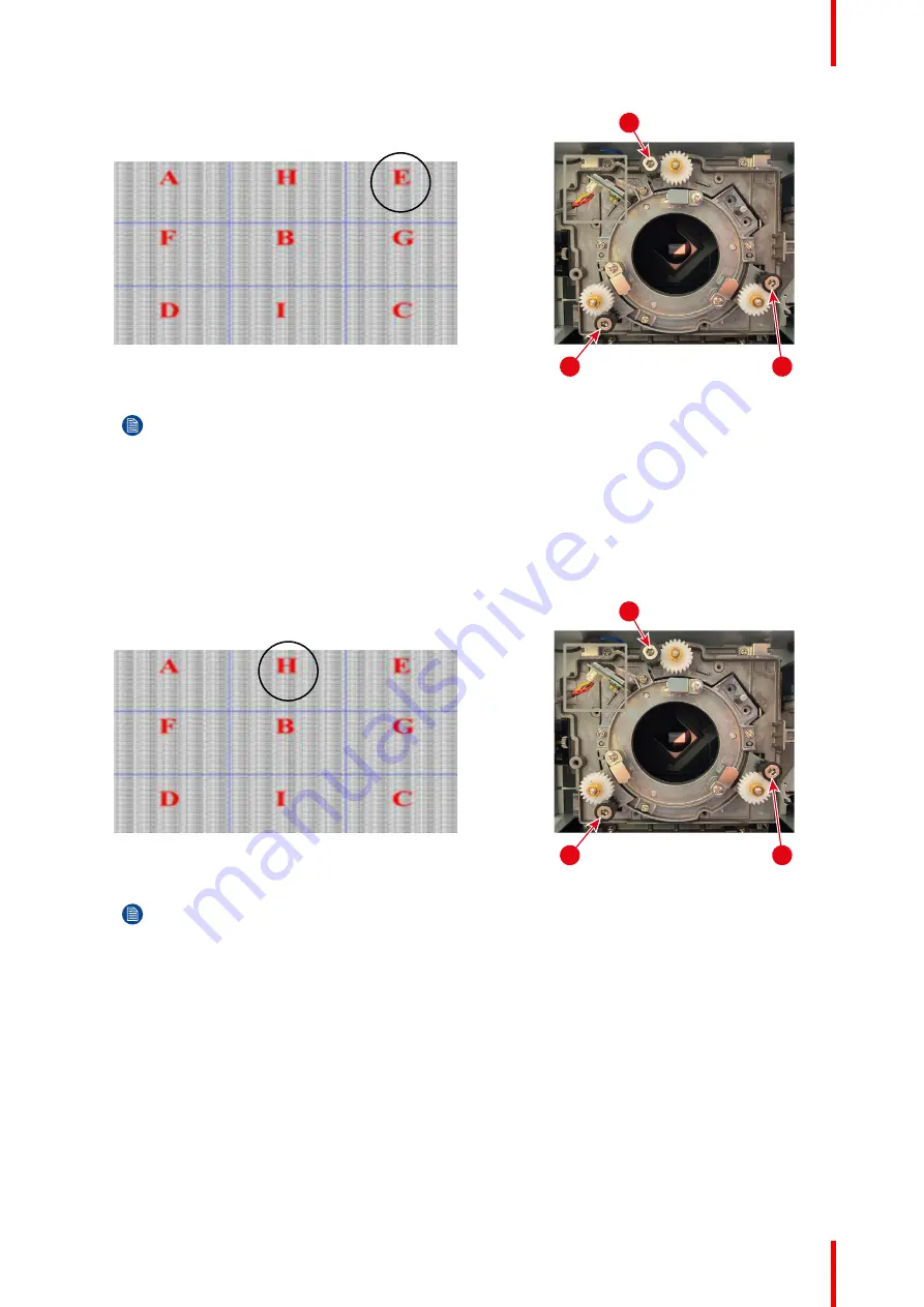
Image 5–8
Note:
This process may cause the other areas of the image to slide out of focus. This is totally
normal.
4.
If zone H is in focus on the screen, please check the focal plane of zone I.
•
If clear position is just on the screen→ No need to adjust.
•
If clear position is out of the screen(cloe to projector), rotate screw
③
CCW and then screw
①
&
②
CW
for half amount that
③
rotated. → repeat until both H and I are clear. (e.g. turning
③
CCW in a circle,
then turn
①
&
②
CW in half circle).
•
If clear position is in the screen(far from projector), rotate screw
③
CW and then screw
①
&
②
CCW
for half amount that
③
rotated. → repeat until both H and I are clear.
1
3
2
Image 5–9
Note:
This process may cause the other areas of the image to slide out of focus. This is totally
normal.
5.
After the above adjustment of the viewing axis, the projected image from zone A to zone I still cannot
achieve a clear focus on the screen. Please turn the boresight screws
①
to
③
counterclockwise to the end
(STOP), and then turn clockwise 2 circles to the design value position. To improve the focus, go to step 2
and repeat the complete procedure.
Summary of Contents for G50
Page 1: ...ENABLING BRIGHT OUTCOMES Installation manual G50...
Page 4: ......
Page 44: ...R5916677 00 G50 44 Installation procedures...
Page 56: ...R5916677 00 G50 56 Adjusting the projected image...
Page 72: ...R5916677 00 G50 72 List of tools...
Page 75: ......


