


16. FLM liquid cooling circuit
16.10 Calibrating the liquid cooling circuit
To check if the pressure vessel is correctly calibrated you may connect the syringe with the cooling circuit
and measure the amount of liquid that is automatically expelled. The pressure would have dropped from 1 to
0 bar. The expelled amount of cooling liquid should be between 50 and 70 ml. Make sure that there are no air
bubbles in the syringe while doing this. Reinject the expelled liquid back into the circuit. The pressure would
hence return to 1 bar.
A calibrated liquid cooling circuit means that the ratio between the volume of cooling liquid in the circuit and
the volume of air in the pressure vessel is defined. This is achieved by first filling the vessel completely with
liquid consequently expelling air from the vessel. Secondly a predefined volume of cooling liquid is extracted
from the circuit. Finally the liquid cooling circuit has to be pressurized to 1 bar by pumping air into the vessel.
Make sure that all air is expelled from the liquid cooling circuit before starting the calibration procedure.
Necessary tools
•
Half a meter of plastic tube with female valved fitting.
•
Syringe connected with short tube with male valved fitting.
•
Bottle with cooling liquid.
•
Air pump.
•
Cloths.
How to calibrate the liquid cooling circuit ?
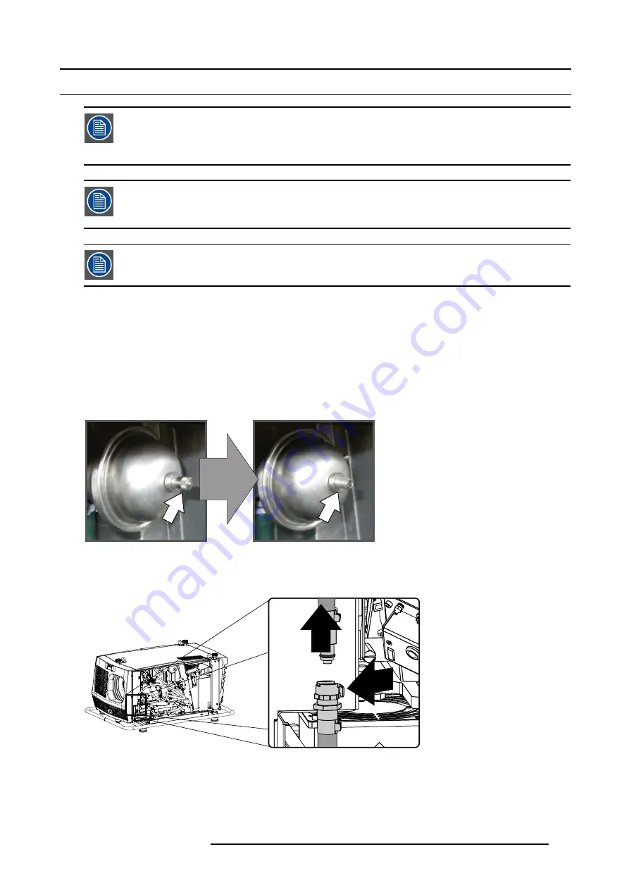
1. Remove the valve cap of the pressure vessel and release the pressure.
Image 16-32
2. Interrupt the liquid cooling circuit by uncoupling the valved fitting at the heat exchanger if not yet done.
Tip:
Sometimes a little cooling liquid will be spilled. Wrap a small cloth around the valved fitting while uncoupling to absorb
the spilled cooling liquid.
2
1
Image 16-33
3.
Fill the syringe with cooling liquid as follows:
R59770072 FLM SERIES 19/03/2007
175
Summary of Contents for FLM series
Page 1: ...FLM series Service manual R59770072 00 19 03 2007...
Page 6: ...Table of contents 4 R59770072 FLM SERIES 19 03 2007...
Page 10: ...1 Safety 8 R59770072 FLM SERIES 19 03 2007...
Page 86: ...6 Removal and installation of projector covers 84 R59770072 FLM SERIES 19 03 2007...
Page 96: ...8 Lamp and lamp house 94 R59770072 FLM SERIES 19 03 2007...
Page 102: ...9 Input communication unit 100 R59770072 FLM SERIES 19 03 2007...
Page 125: ...13 Cold mirror assembly Image 13 5 Remove of cold mirror R59770072 FLM SERIES 19 03 2007 123...
Page 130: ...13 Cold mirror assembly 8 Reinstall the side cover 128 R59770072 FLM SERIES 19 03 2007...
Page 133: ...14 Lens holder F Image 14 4 R59770072 FLM SERIES 19 03 2007 131...
Page 140: ...14 Lens holder 138 R59770072 FLM SERIES 19 03 2007...
Page 154: ...15 Vertical and Horizontal shift motors 152 R59770072 FLM SERIES 19 03 2007...
Page 180: ...16 FLM liquid cooling circuit 178 R59770072 FLM SERIES 19 03 2007...
Page 190: ...17 Heat exchanger 188 R59770072 FLM SERIES 19 03 2007...
Page 204: ...18 Cooling pump 202 R59770072 FLM SERIES 19 03 2007...
Page 208: ...19 Shutter replacement 206 R59770072 FLM SERIES 19 03 2007...
Page 212: ...20 Formatter Interface Board 210 R59770072 FLM SERIES 19 03 2007...
Page 217: ...21 Pixel map processor board Image 21 7 PMP removal R59770072 FLM SERIES 19 03 2007 215...
Page 220: ...21 Pixel map processor board 218 R59770072 FLM SERIES 19 03 2007...
Page 228: ...22 LCD panel replacement 226 R59770072 FLM SERIES 19 03 2007...
Page 234: ...23 Keypad board replacement 232 R59770072 FLM SERIES 19 03 2007...
Page 288: ...25 Peltier replacement 286 R59770072 FLM SERIES 19 03 2007...
Page 314: ...28 Start pulse generator 312 R59770072 FLM SERIES 19 03 2007...
Page 326: ...Glossary 324 R59770072 FLM SERIES 19 03 2007...


