4-5
CLM W6_CLM HD6 Jan 3, 202
Chapter 4 Function Test & Alignment Procedure
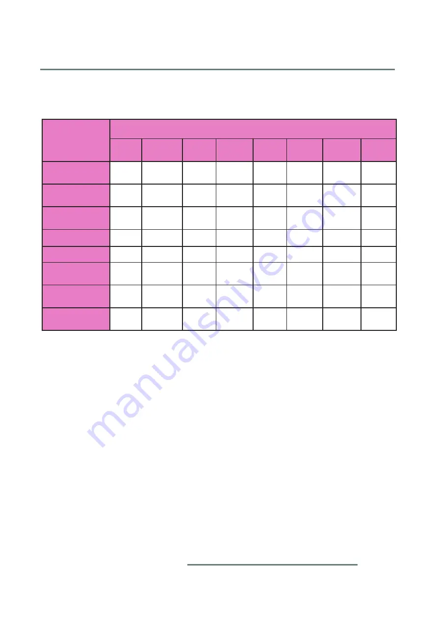
4-6 Test Inspection Procedure
Update
Change parts
Main
Board Firmware
Color
Wheel
Lamp
Module
ROD
Module
Keypad
Board
Fan or
Blower
LAN
Board
Firmware version
update
v
Color Wheel
Index
v
v
Reset Lamp
Hour
v
Factory Reset
v
v
Rod adjustment
v
F-type Fan
calibration
v
v
Re-write Serial
Number
v
Upgrade
Network FW
v
Note: - If Color appears abnormal after changing Main Board Module, please get into Hidden Menu
to do Color Wheel index adjustment.
- After changing parts, check the information above table.
- When change below fan,
F-type Fan calibration
is needed:
Item 13--> F-Fan 11;
Item 14--> F-Fan 10;
Item 15--> F-Fan 13;
Item 21--> F-Fan 12
Please refer to the table of connector board on page 2-20 of Chapter 2 for more details.
Summary of Contents for CLM W6
Page 1: ...CLM W6 HD6 Service Manual ...
Page 10: ...1 CLM W6_CLM HD6 Jan 31 2012 Chapter 1 Introduction 1 2 System block diagram ...
Page 11: ...1 CLM W6_CLM HD6 Jan 31 2012 Chapter 1 Introduction 1 3 Main board connection diagram ...
Page 66: ...Chapter 2 Disassembly Process 2 55 CLM W6_CLM HD6 Jan 31 2012 5 Disassembly is completed ...
Page 74: ...3 5 Image Performance Troubleshooting Chapter 3 Troubleshooting 3 CLM W6_CLM HD6 Jan 31 2012 ...
Page 75: ...3 5 Image Performance Troubleshooting Chapter 3 Troubleshooting 3 CLM W6_CLM HD6 Jan 31 2012 ...
Page 76: ...Chapter 3 Troubleshooting 3 CLM W6_CLM HD6 Jan 31 2012 3 5 Image Performance Troubleshooting ...
Page 78: ...Chapter 3 Troubleshooting 3 11 CLM W6_CLM HD6 Jan 31 2012 3 6 Remote Control Troubleshooting ...
Page 79: ...Chapter 3 Troubleshooting 3 12 CLM W6_CLM HD6 Jan 31 2012 3 7 Network Troubleshooting ...
Page 119: ... CLM W6_CLM HD6 Jan 31 2012 Appendix A Exploded Image 1 2 3 4 4 5 ASSY ENGINE MODULE ...


