Chapter 2 Disassembly Process
2-4
CLM W6_CLM HD6 Jan 3, 202
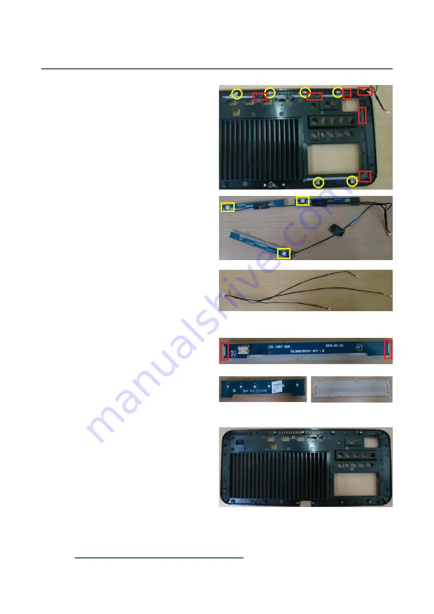
6. Unscrew 6 screws (yellow circle),
remove LED module.
Repair note: - Please stick the 6 mylar (red
square) as it was when assemble
LED module.
7. Unplug 3 connectors (yellow square),
remove LED cable.
8. Open 6 clips (red square), separate
LED light Bar and LED light holder.
9. Disassemble I/O cover.
LED light holder
LED light Bar
Summary of Contents for CLM W6
Page 1: ...CLM W6 HD6 Service Manual ...
Page 10: ...1 CLM W6_CLM HD6 Jan 31 2012 Chapter 1 Introduction 1 2 System block diagram ...
Page 11: ...1 CLM W6_CLM HD6 Jan 31 2012 Chapter 1 Introduction 1 3 Main board connection diagram ...
Page 66: ...Chapter 2 Disassembly Process 2 55 CLM W6_CLM HD6 Jan 31 2012 5 Disassembly is completed ...
Page 74: ...3 5 Image Performance Troubleshooting Chapter 3 Troubleshooting 3 CLM W6_CLM HD6 Jan 31 2012 ...
Page 75: ...3 5 Image Performance Troubleshooting Chapter 3 Troubleshooting 3 CLM W6_CLM HD6 Jan 31 2012 ...
Page 76: ...Chapter 3 Troubleshooting 3 CLM W6_CLM HD6 Jan 31 2012 3 5 Image Performance Troubleshooting ...
Page 78: ...Chapter 3 Troubleshooting 3 11 CLM W6_CLM HD6 Jan 31 2012 3 6 Remote Control Troubleshooting ...
Page 79: ...Chapter 3 Troubleshooting 3 12 CLM W6_CLM HD6 Jan 31 2012 3 7 Network Troubleshooting ...
Page 119: ... CLM W6_CLM HD6 Jan 31 2012 Appendix A Exploded Image 1 2 3 4 4 5 ASSY ENGINE MODULE ...


