


7
www.bannerengineering.com - Tel: +1-763-544-3164
P/N 148770 Rev. F
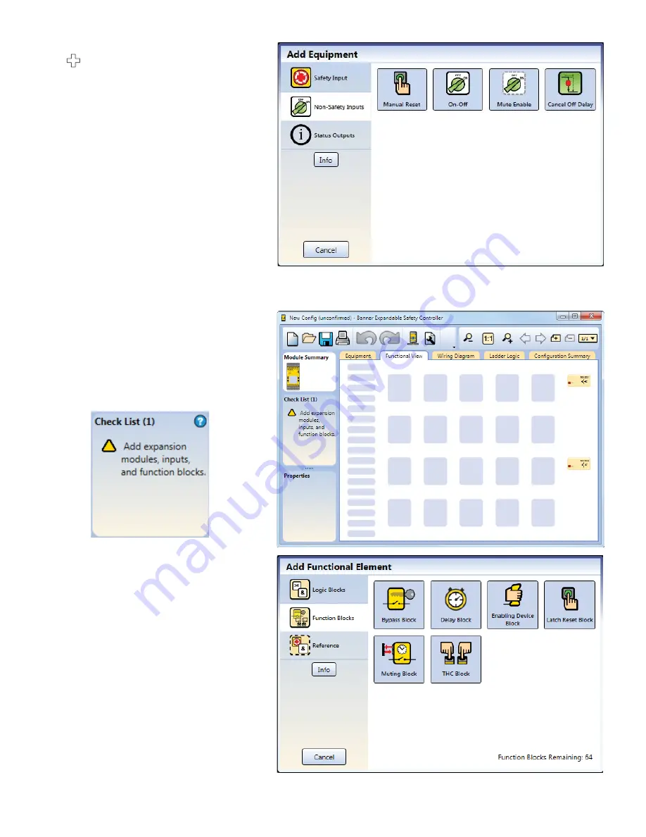
3. Add
Non-Safety Inputs
by clicking
under the Base Module:
• Manual Reset
Create Connections
4. Go to
Functional View
.
Note:
The
Check List
on the left lists
any missing connections that need to be
added before the con
fi
guration is valid.
5. Add the
Function Blocks
by clicking
on one of the empty placeholders in
the middle area:
• Latch Reset Block


