


5
www.bannerengineering.com - Tel: +1-763-544-3164
P/N 148770 Rev. F
1
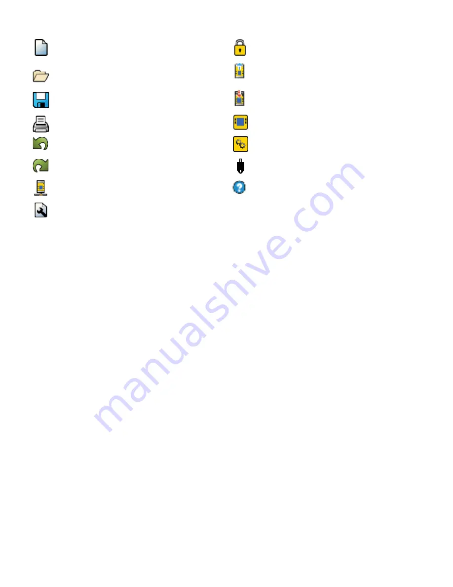
Navigation Toolbar
Starts a New Project or opens a Recent project
and Sample Con
fi
gurations
Displays Password Manager
Opens an existing project
Reads data, such as Fault Log, Con
fi
guration,
Network Settings, and Device Information, from
the Safety Controller
Saves (or Saves As) the project to the user-
de
fi
ned location
Writes the data, such as Con
fi
guration and/or
Network Settings, to the Safety Controller
Prints a customizable Con
fi
guration Summary
Makes the Live Mode view available
Reverts up to ten previous actions
Makes the Simulation Mode View available
Re-applies up to ten previously reverted actions
Indicates SC-XM2 drive connection
Displays Network Settings
Opens the Help options
Displays Project Settings
2
Tabs
• Equipment
—displays an editable view of all connected equipment.
• Functional View
—provides an editable iconic representation of the control logic.
• Wiring Diagram
—displays the I/O device wiring detail for use by the installer.
• Ladder Logic
—displays a symbolic representation of the Controller’s safeguarding logic for the use by
the machine designer or controls engineer.
• Industrial Ethernet (when enabled)
—displays editable network con
fi
guration options.
• Confi guration Summary
—displays a detailed con
fi
guration summary.
• Live Mode (when enabled)
—displays the live mode data, including current faults.
• Simulation Mode (when enabled)
—displays the simulation mode data
3
Selected view
Displays the view corresponding to the selected tab (
Equipment
view shown).
4
Module Summary
Displays the Base Controller and any connected modules.
5
Checklist
Provides action items to con
fi
gure the system and correct any errors to successfully complete the
con
fi
guration.
6
Properties
Displays the properties of the selected device, function block, or connection (properties cannot be edited in
this view, click Edit to make changes).


