Banner XS26-2 Series Quick Start Manual Download Page 2

2

www.bannerengineering.com - Tel: +1-763-544-3164

P/N 148770 Rev. F

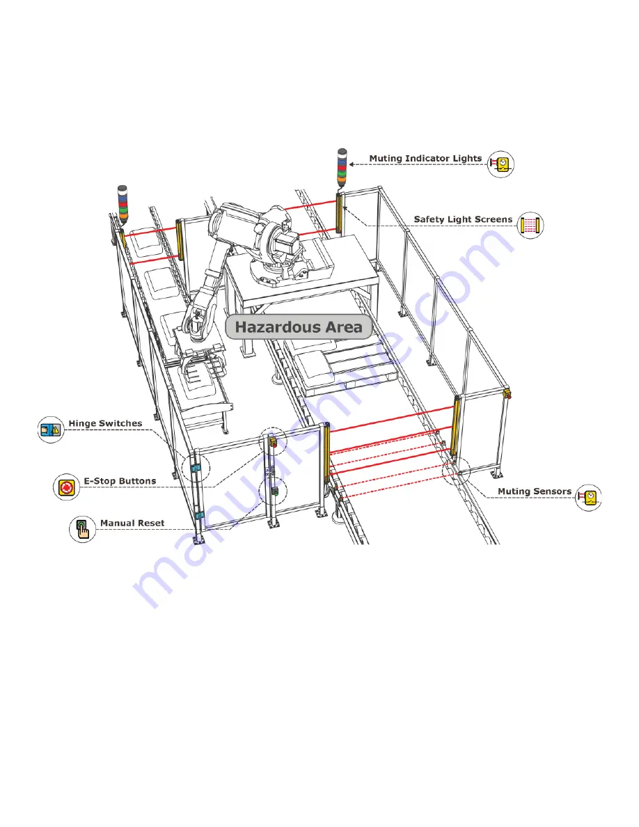
Designing a Sample Confi guration

The con

fi

 guration process used in this guide provides basic understanding of the software features that are 

necessary to create a con

fi

 guration for any application. The example con

fi

 guration is based on a sample 

application which makes use of the following devices:  an XS/SC26-2 Safety Controller, an E-stop button, a 

Safety Light Curtain, an Interlocked Gate Switch, and a Manual Reset. The illustration below depicts these 

devices and additional safety equipment for a sample Robotic Cell application.

Summary of Contents for XS26-2 Series

Page 1: ...r PC Interface For complete information on mounting device installation and operation commissioning checkout procedures product specifications troubleshooting and glossary please refer to the Safety C...

Page 2: ...that are necessary to create a configuration for any application The example configuration is based on a sample application which makes use of the following devices an XS SC26 2 Safety Controller an E...

Page 3: ...rom www bannerengineering com xs26 Important Administrative rights are required to install the Safety Controller drivers needed for communication with the controller To install the software from the B...

Page 4: ...4 www bannerengineering com Tel 1 763 544 3164 P N 148770 Rev F Designing a Configuration Open XS26 2 Expandable Safety Controller from the Desktop or the Start Menu PC Interface Features...

Page 5: ...equipment Functional View provides an editable iconic representation of the control logic Wiring Diagram displays the I O device wiring detail for use by the installer Ladder Logic displays a symboli...

Page 6: ...thor Person designing the configuration Notes Supplemental information for this configuration or project Project Date Date pertaining to the project Add Equipment 1 On the Equipment view select your B...

Page 7: ...der the Base Module Manual Reset Create Connections 4 Go to Functional View Note The Check List on the left lists any missing connections that need to be added before the configuration is valid 5 Add...

Page 8: ...s to 3 8 Connect Optical Sensor Gate Switch and Latch Reset Block to one of the input nodes on the AND block 9 Connect Emergency Stop and Manual Reset to the Latch Reset Block 10 Connect the AND block...

Page 9: ...anties All specifications published in this document are subject to change Banner reserves the right to modify product specifications or update documentation at any time Specifications and product inf...

Reviews: