background image

2. Release the button to enter the Auto Learn function. The reader begins to automatically detect and recognize

barcodes (by type and length) that are presented to it

3

. The laser turns on and the LEARN LED blinks to indicate

the ongoing process.

SETUP

LEARN

TEST

READY 

GOOD 

TRIGGER

COM 

STATUS 

green 

green 

yellow 

yellow 

red

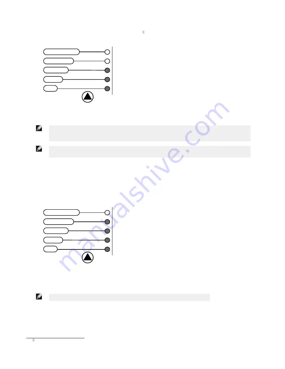
1. Place the desired barcode on the scanline.
2. Wait until the LEARN LED is steady ON (indicating the

reader has detected the barcode).

3. Repeat, if needed, the above two steps to program up to

10 different barcodes (the LEARN LED returns to the

blinking state for the next code). If more than one barcode

is detected in the scan line, the Multi Label mode is

enabled (refer to TCNM-AD/EX/SP Family Software

Configuration Parameter Guide help file).

3. Exit the process by pressing the SMART-TEACH push button once. The scanner restarts at the end of the process,

and then the detected barcodes are automatically configured in the scanner memory.

NOTE: If the barcode cannot be read because of low contrast or excessive ambient light, you can

perform the AutoSetup function to optimize the optical parameters. Then you can perform Auto Learn to

recognize the barcode symbology.

NOTE: On exit from Auto Learn, the following parameters are forced: Code Combination = Single Label,

Reading Mode = Linear. If necessary, these parameters can be changed through GeniusPlus.

Auto Setup (Optional)

At the end of the Auto Learn procedure, you may follow the Auto Setup procedure to set up the reading parameters.

1. Hold the SMART-TEACH push button pressed until the SETUP LED is on.
2. Release the button to enter the Auto Setup function.
3. Once entered, if a barcode label is positioned in front of the scanline, the scanner automatically performs the

optimal setup of the reading parameters for that specific barcode.

SETUP

LEARN

TEST

READY 

GOOD 

TRIGGER

COM 

STATUS 

green 

green 

yellow 

yellow 

red

1. Place the desired barcode on the scanline.
2. Enter the Auto Setup function (the laser turns on and the

SETUP LED blinks to indicate the ongoing process).

3. Wait until the SETUP LED stays steady ON (indicating the

reader has detected the barcode).

This procedure ends either when the barcode is successfully decoded or after a timeout of about 7 seconds. The scanner

restarts at the end of the process, and then the optimized reading parameters for that barcode are automatically

configured in scanner memory.

NOTE: If your application has been configured using SMART-TEACH, go to STEP 5.

Reset Scanner to Factory Default (Optional)

To reset the scanner to the factory default values, hold down the SMART-TEACH push button while powering up the

scanner. At the end of the procedure (about 5–6 seconds), the Configuration and Environmental parameters are reset, and

all LEDs blink simultaneously three times.

3 In case of Programming Barcodes, refer to the “Setup Procedure Using Programming Barcodes” document in the product CD.


TCNM-AD Barcode Scanner

6

www.bannerengineering.com - tel: 763-544-3164

P/N 175718 Rev. A

Summary of Contents for TCNM-AD

Page 1: ...plication For a pass through installation refer to the appropriate section For complete scanner configuration using the GeniusPlus configuration program refer to the Context Sensitive Help On Line To connect the system in a standalone configuration you need the hardware indicated below In this layout the data is transmitted to the Host on the main serial interface In Local Echo communication mode ...

Page 2: ...nd O1 Output 1 O1 Output 1 Inputs O2 Output 2 V Power Source External Trigger O2 Output 2 I1A External Trigger A polarity insensitive Auxiliary Interface I1B External Trigger B polarity insensitive TX Auxiliary Interface TX V Power Reference External Trigger RX Auxiliary Interface RX V Power Source Inputs SGND Auxiliary Interface Reference I2A Input 2 A polarity insensitive ID NET I2B Input 2 B po...

Page 3: ...pin connector 13 25 14 1 Figure 2 25 pin male D sub connector 25 pin D sub male connector pinout Pin Name Function 13 9 Vdc Power supply input voltage 25 7 GND Power supply input voltage 1 CHASSIS Cable shield connected to chassis 18 I1A External Trigger A polarity insensitive 19 I1B External Trigger B polarity insensitive 6 I2A Input 2 A polarity insensitive 10 I2B Input 2 B polarity insensitive ...

Page 4: ...ew Tilt Skew Pitch Figure 3 Positioning with mounting bracket 2 When mounting the barcode scanner take into consideration these three ideal label position angles Skew 10 to 30 Tilt 0 and Pitch 0 Ensure at least 10 Minimize Tilt Angle Minimize Pitch Angle S T P Skew Angle Figure 4 Skew Tilt and Pitch Angles 3 Refer to the Reading Diagrams to determine the distance at which your scanner should be po...

Page 5: ...ce the Oscillating Mirror remains in the default fixed position 15 to make barcode reading easier while performing the SMART TEACH functions Table 1 Indicators Label Color Meaning READY Green Indicates the device is ready to operate GOOD Green Confirms successful reading TRIGGER Yellow Indicates the status of the reading phase COM Yellow Indicates active communication on main serial port STATUS Re...

Page 6: ...the end of the Auto Learn procedure you may follow the Auto Setup procedure to set up the reading parameters 1 Hold the SMART TEACH push button pressed until the SETUP LED is on 2 Release the button to enter the Auto Setup function 3 Once entered if a barcode label is positioned in front of the scanline the scanner automatically performs the optimal setup of the reading parameters for that specifi...

Page 7: ...assumes scanner connection to a TCNM ACBB1 GeniusPlus running on a laptop computer is connected to the scanner auxiliary port through the TCNM ACBB1 9 pin connector To communicate with the scanner GeniusPlus performs an auto baud rate detection starting from its default parameters which are 115200 8 N 1 These parameters can also be set in the GeniusPlus Tools Options Communications window Wizard f...

Page 8: ...r When working in this mode the reader is continuously scanning while the reading phase is activated each time a barcode enters the reader reading zone The reader stops reading after an N number of scans without a code Barcode characters are transmitted on the serial interface In case of a failed reading phase no message is sent to the host computer c Configure one or both digital outputs by selec...

Page 9: ...fining the parameter values the following window appears allowing you to complete the reader configuration as follows Save the configuration to disk Switch to Advanced Mode Send the configuration to the scanner TCNM AD Barcode Scanner P N 175718 Rev A www bannerengineering com tel 763 544 3164 9 ...

Page 10: ... 1 To enter Test Mode hold down the SMART TEACH push button until the TEST LED is on 2 Once entered the bar graph on the five LEDs is activated and if the scanner starts reading barcodes the bar graph shows the Good Read Rate In case of no read condition only the STATUS LED is on and blinking SETUP LEARN TEST READY GOOD TRIGGER COM STATUS green green yellow yellow red TCNM AD Barcode Scanner 10 ww...

Page 11: ...m a host computer using the Host Mode programming procedure and commands via the serial interface See the Host Mode Programming file on the CD Alternative Layouts The ID NET network is a built in speed interface dedicated for high speed scanner interconnection ID NET is in addition to the Main and Auxiliary serial interfaces If you need an ID NET network refer to the TCNM AD EX manual The scanner ...

Page 12: ...ndard Resolution TCNM AD 2200 High Resolution TCNM AD 1204 Standard Resolution TCNM AD 2204 High Resolution Note 0 0 is the center of the laser beam output window TCNM AD Barcode Scanner 12 www bannerengineering com tel 763 544 3164 P N 175718 Rev A ...

Page 13: ...0 40 mm 1 6 in 300 mm 11 8 in on 0 50 mm 20 mils codes 12X4 50 mm 1 8 in 310 mm 11 8 in on 0 50 mm 20 mils codes 22X0 30 mm 1 2 in 90 mm 3 5 in on 0 30 mm 12 mils codes 22X4 30 mm 1 2 in 90 mm 3 5 in on 0 30 mm 12 mils codes Refer to the diagrams given in Reading Diagrams for further details on the reading features They are taken on various resolution sample codes at a 25 C ambient temperature dep...

Page 14: ...sistance N 60068 2 29 30g 6 ms 5000 shocks on each axis Environmental Rating IP65 Protection Class EN 60529 Dimensions 68 x 84 x 34 mm 2 7 x 3 3 x 1 3 in Weight 330 g 11 6 oz LED Indicators Ready Good Trigger Com Status Power On Multi function Key SMART TEACH button Software Readable Codes EAN UPC including Add on 2 and Add on 5 7 2 5 Interleaved7 ABC Codabar Codabar7 Code 39 Standard and Full ASC...

Page 15: ...acket and may be used for installation 23 3 0 92 14 0 55 84 3 31 4 0 16 10 3 0 41 40 1 57 0 41 10 3 40 1 57 14 7 0 58 M 4 n 4 1 29 32 7 mm inch 68 2 68 46 1 81 The quote refers to the scan line Figure 5 Overall Dimensions 9 4 2 7 8 20 2 5 73 42 R 4 0 4 2 90 30 13 8 17 5 2 5 23 units in mm 4 2 n 2 1 x 45 n 2 Figure 6 Mounting Bracket Overall Dimensions 7 ACR Readable TCNM AD Barcode Scanner P N 175...

Page 16: ...ight and the device classification are applied onto the body of the scanner Disconnect the power supply when opening the device during maintenance or installation to avoid exposure to hazardous laser light The laser diode used in this device is classified as a class 3B laser product according to EN 60825 1 regulations and as a Class IIIb laser product according to CDRH regulations Any violation of...

Page 17: ...precision product and it must be handled correctly before and during installation to avoid damage Avoid that the scanners hit one another causing damage They should be handled separately Avoid that the scanners are dropped exceeding shock limits Do not fine tune the positioning by striking the scanner or bracket Do not weld the scanner into position this can cause electrostatic heat or output wind...

Reviews: