background image

4

Supply Power to the Emitter-Receiver Directional Sensor Pair and Mount to 
the Bracket

The Directional Sensor Pair comes with two components: an emitter and a receiver with an internal radio. 

Set Up Your Hardware

Supply power to all devices 

The Occupancy Monitoring Kit arrives with all necessary power sources needed to get the system operating quickly. This 
includes lithium batteries for the Directional Sensors and Direct Select Operator Interface, and a DC power supply for the DXM 
Controller and TL70 Wireless Indicator Light.

1

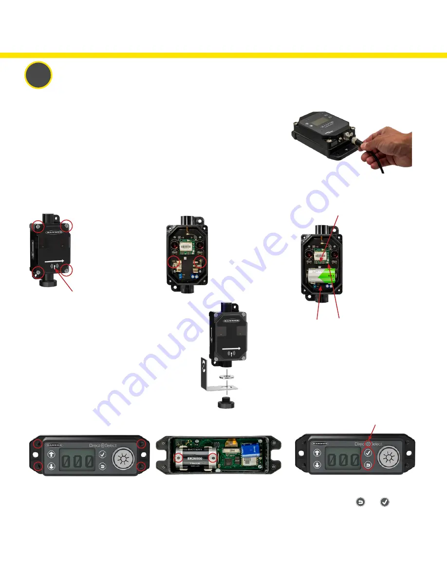
Supply Power to the DXM Controller

Plug the power supply into the DXM Controller, aligning the keys in the connector, and 
hand tighten. Plug the power supply into a power outlet using the appropriate regional wall 
adapter.

3. If the Status LED does not automatically 
begin flashing, turn on the Operator Interface 
by pressing and holding 

 and 

 together 

for five seconds or until the Status LED starts 
flashing red.
4. Reassemble the Node and tighten the four 
corner screws. Do not over-tighten.

Supply Power to the Direct Select Operator Interface

1. Unscrew the four corner screws with a 
Phillips screwdriver and open the Operator 
Interface.

2. Insert the 3.6 V lithium battery. Verify the 
battery’s positive and negative terminals align 
to the positive and negative terminals as 
marked. 
Caution: There is risk of damage if the 
batteries are installed incorrectly.

Status LED

1. Unscrew the four corner 
screws with a Phillips 
screwdriver on the Receiver 
and remove the cover. 
The Receiver has an internal 
radio with a radio icon on the 
base and front cover.

4. Place the cover back on the Receiver and hand tighten 
the four corner screws. Do not over-tighten. 
5. Mount the supplied bracket to the Receiver. Place the L 
bracket between the washer and the jam nut. Thread the 
jam nut onto the base of the Receiver. Hand-tighten the 
jam nut.
Repeat this process for the Emitter.

2. Insert the 3.6V lithium 
D cell battery. Verify the 
battery's positive and 
negative terminals align to 
the positive and negative 
terminals as marked.
Caution: there is risk of 
damage if the batteries are 
installed incorrectly.

3. If the radio board 
Status LED does not 
automatically begin 
flashing, turn on the 
radio by pressing and 
holding the button until it 
begins flashing. 
Verify the toggle switch 
on the bottom of the 
sensor is in the “ON” 
position.

Radio 
button

Status LED

Radio icon

Toggle 
switch

Summary of Contents for TCER

Page 1: ...219271 Rev A Occupancy Solution Kit Total Count Emitter Receiver TCER Setup Guide ...

Page 2: ...icator includes bracket and power supply Receiver includes D cell battery and ISM radio DXM Controller Not shown above Direct Select Operator Interface includes C battery Power Supply Tools Needed Tape measure Phillips screwdriver Hand drill Emitter includes D cell battery ...

Page 3: ...enclosures The Emitter Receiver Directional Sensor Pair detects whether a person is entering or exiting the monitored area The sensor pair comes with two components an emitter and a receiver with an internal radio The receiver has a radio icon on the cover and base of the sensor Mount the sensor pair according to Banner s suggested mounting instructions The Direct Select Operator Interface display...

Page 4: ... corner screws with a Phillips screwdriver and open the Operator Interface 2 Insert the 3 6 V lithium battery Verify the battery s positive and negative terminals align to the positive and negative terminals as marked Caution There is risk of damage if the batteries are installed incorrectly Status LED 1 Unscrew the four corner screws with a Phillips screwdriver on the Receiver and remove the cove...

Page 5: ...ored area Mount the sensors using two 1 4 20 mounting bolts self tapping screws or the optional magnetic brackets Use the side arrows on the Emitter and Receiver to mount the sensor in the correct orientation When mounting the Directional Sensor Pair using the supplied brackets 1 Mount the Emitter bracket to a rigid surface 2 Mount the Receiver bracket at the same height as the Emitter bracket Fol...

Page 6: ... where people will stand and block the sensors Inward Opening Doors For occupancy monitoring in areas with inward opening doors Banner recommends mounting the devices on the inside of the door and far enough from the door that the door does not block the sensor pair when opening The supplied bracket allows for sensor rotation for an angled mounting The sensors should be mounted to the supplied bra...

Page 7: ...Registers menu and press ENTER Highlight Occupancy Limit and press ENTER Enter your desired Occupancy Limit 1 Using the up and down arrow buttons select the first digit for the limit and press ENTER to set the first digit 2 Use the up and down arrows to set the second digit and press ENTER 3 Repeat if you are adding a third digit 4 Press ENTER once more to highlight SEND and press ENTER to confirm...

Page 8: ...e reset schedule Operator Interface no longer displays the counts After the DXM Controller is rebooted a delay of 5 minutes may occur before counts are displayed The Operator Interface may not be communicating with the DXM Controller Check the status LED above the check mark button If the status LED flashes red change the positioning of the DXM Controller or Operator Interface so that they are clo...

Page 9: ...s if directed to by your IT department Setting a Static IP Address To define a specific IP address of your choosing 1 On the DXM use the arrows and move to the System Config menu Press ENTER 2 Use the arrow keys to select the Ethernet menu Press ENTER 3 Highlight the DHCP selection and press ENTER Set DHCP to OFF 4 The system will request a restart press ENTER to confirm 5 Follow steps 1 and 2 to ...

Page 10: ... the DXM s main menu scroll to System Info and then press ENTER twice to view the seven digit serial number at the bottom of the information list 3 Enter all seven digits into the DXM Serial entry field on Banner CDS 4 Verify that Configuration is set to Solutions and select Occupancy Total Count for the Kit Type This allows the Banner CDS application to automatically create Dashboard layouts and ...

Page 11: ...w profile 30 mm mounting hole 300 series stainless steel No fasteners included Optional Accessories Warning Indicator Segment SG TL70 Y Used with the TL70 Wireless Indicator Light Yellow indicator for Warning indication View Dashboard and Set Parameters After Banner CDS has created the site and detected the DXM Controller click on Go to Dashboard Go to Dashboard The Dashboard panel appears and ind...

Page 12: ...Banner Engineering Corp 9714 Tenth Avenue North Minneapolis Minnesota 55441 763 544 3164 1 888 373 6767 www bannerengineering com 2020 Banner Engineering Corp Mpls MN USA 219271 Rev A ...

Reviews: