background image

The requirements for electrical safety and electromagnetic compatibility and the regulations or standards in all
countries and/or regions, must be met by the power supply where the laser scanner is used. If the device power
supply is shared with the machine or other electronic devices, voltage fluctuations to the laser scanner or noise
influences to the scanner may occur due to temporary changes of the current consumption on the machine or the
other electronic devices. We do not recommend sharing the laser scanner power supply with the one for the machine
or the other electronic devices, because the device may go to an error state in such circumstances.

Do not run the connection cables in contact with or near high-voltage cables and/or cables which undergo large
current variations (i.e. motor power supplies, inverters, etc.).

Access to the configuration tools must be restricted to only highly qualified personnel. The configuration upload
process through the GUI is allowed only by password.

2.12 Specifications

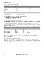
Power Consumption

No output load (P

0

) at 24 V DC: 8 W for a stand-alone scanner

No output load (P

0

) at 24 V DC : 8 W + 8 W for each remote scanner for

a master scanner

With maximum output load at 24 V DC: P0 plus 12 W per OSSD pairs

used (or Warning pair outputs)

Power-up delay: 40 seconds, typical

Current Consumption (24 V DC)

No output load (I

0

) at 24 V DC: 0.3 A for a stand-alone scanner

No output load (I

0

) at 24 V DC: 0.3 A plus 0.3 A for each remote scanner

for a master scanner

With maximum output load at 24 V DC: I

0

 plus 0.5 A per OSSD pair used

(or warning pair outputs)

Static Input Generic

Input voltage high: > 12 V

Input voltage low: < 5 V

Input current high: 2 mA at 24 V DC

Input impedance: 12 kΩ

Connectors

I/O and power: M12 male type A connector (8/12/17 pins)

Ethernet to GUI or Data transmission: M12 male type D connector (4-

pin)

Master to Remote and Remote to Remote: M12 male type A connector

(8-pin)

Power and Electrical Protection

Protection class: III ( EN 61140 / IEC 61140 )

Supply voltage: Uv 24 V DC (19.2 V … 30 V DC) (SELV/PELV)

2

Residual ripple: ± 5% 

3

Start-up current (1): < 0.6 A 

4

The Scanner should be connected only to a SELV (Safety Extra-Low

Voltage) for circuits without earth ground or a PELV (Protected Extra-

Low Voltage) for circuits with earth ground power supply.

Light Beam Diameter

At front screen: 8 mm

At middle field distance: 10 mm

At max distance: 20 mm

Detectable remission: 1.8% to 1000%

Maximum homogeneous contamination of the optics cover without

preventing the detection capability –30% of nominal optic power

Output (warning and generic)

Output logic and protection: PUSH-PULL, Overcurrent protection

Output voltage for ON status (HIGH): Uv – 2 V at 250 mA

Output voltage for OFF status (LOW): ≤ 0.2 V

Output current for ON status (HIGH): 250 mA

Leakage current: < 700 μA 

5

Load inductance: 2 H

Load capacity: 2.2 µF

Optical Data

Wavelength: 905 nm

Pulse duration: 3 nsec

Average output power: 8 mW

Laser class: CLASS 1 (EN 60825-1: 2014)

Divergence of collimated beam: 0.12°

Mechanical Data

Dimensions (W × H × D): 102 × 152 × 112.5

Weight (including system plug): 1.5 kg

Housing material: Aluminum Alloy

Housing color: Yellow RAL1003

Optics cover material: PC

Optics cover surface: Acrylic

OSSD (Safety Output)

OSSD logic and protection: PUSH-PULL, Overcurrent protection

Output voltage for ON status (HIGH): Uv – 2 V at 250 mA

Output voltage for OFF status (LOW): ≤ 0.2 V

Output current for ON status (HIGH): 250 mA

Leakage current: < 700 μA 

6

Max Load inductance: 2 H

Max Load capacity: 2.2 µF

Test pulse width: 115 µs (typical)

Test period on a single OSSD: 900 ms (typical)

Test pulse shift time between OSSD outputs in a pair: 150 ms (typical)

Test pulse shift time between OSSD outputs (separate pairs): 300 ms

(typical)

2

To meet the requirements of the relevant product standards (e.g. EN 61496-1), the external voltage supply for the devices (SELV) must be able to bridge a brief mains failure of 20 ms.
Power supplies according to EN 60204-1 satisfy this requirement.

3

The absolute voltage level must not drop below the specified minimum voltage.

4

The load currents for the input capacitors are not taken into account.

5

In the case of a fault (0 V cable open circuit) maximally the leakage current flows in the OSSD cable. The downstream controller must detect this status as LOW. A FPLC (fail-safe
programmable logic controller) must be able to identify this status.

6

In the case of a fault (0 V cable open circuit) maximally the leakage current flows in the OSSD cable. The downstream controller must detect this status as LOW. A FPLC (fail-safe
programmable logic controller) must be able to identify this status.

SX Safety Laser Scanner


22

www.bannerengineering.com - Tel: + 1 888 373 6767


Summary of Contents for SX5-B

Page 1: ...SX Safety Laser Scanner Instruction Manual Original Instructions 208913 Rev B 5 February 2021 Banner Engineering Corp All rights reserved 208913 ...

Page 2: ... 26 3 2 1 Unmonitored Areas 27 3 2 2 Adjacent SXs 29 3 2 3 Light Interference 30 3 2 4 Highly Reflective Backgrounds 30 3 2 5 Anti Tamper Function 31 3 2 6 Limited Detection Capability Zone 31 3 2 7 Dust Filtering 32 3 2 8 Anti interference Coding 32 3 2 9 Master and Remote Configurations 33 3 2 10 Shut Off Functionality 33 3 3 Positioning Horizontal Safety Zones for Stationary Applications 33 3 4...

Page 3: ...e Lamp Output 70 6 2 6 Mute Time Limit Backdoor Timer 70 6 2 7 Mute Dependent Override 70 6 2 8 Muting Function T X Bidirectional or L Unidirectional Selection 72 6 3 Encoder Functions 74 6 4 Install the Configuration Software 76 6 5 Software Interface 77 6 5 1 Main Menu 77 6 5 2 Toolbar 78 6 5 3 Status Bar 78 6 5 4 Task Selection 79 6 6 Using the Software 79 6 6 1 Output Configuration 81 6 6 2 Zo...

Page 4: ...tenance 117 11 1 Update the Firmware 117 11 2 Handling the Scanner 117 11 3 Cleaning the Window and Scatter Screen 117 11 4 Window Replacement 118 11 4 1 Replace Your Scanner s Window 119 11 4 2 Calibrate a New Window 122 11 5 Fast Replacement in a System with a Memory Device 123 11 5 1 Fast Replacement of a Memory Device 123 11 5 2 Fast Replacement of the Master Scanner 124 11 5 3 Fast Replacemen...

Page 5: ...es and regulations See ISO 13849 1 ANSI B11 19 and or other appropriate standards Verify that the entire safeguarding system including input devices control systems and output devices is properly configured and installed operational and working as intended for the application Periodically re verify as needed that the entire safeguarding system is working as intended for the application 1 2 Use of ...

Page 6: ...presentative in EU Peter Mertens Managing Director Banner Engineering BV Address Park Lane Culliganlaan 2F bus 3 1831 Diegem Belgium SX Safety Laser Scanner 6 www bannerengineering com Tel 1 888 373 6767 ...

Page 7: ...n the sensing range of the scanner two areas can be monitored simultaneously one is the Safety Zone that is used to detect operators or objects entering a hazardous area the other is the Warning Zone that can be defined with a longer distance than the Safety Zone allowing a configuration to detect objects that are approaching the Safety Zone Configurations can also be created with one Safety Zone ...

Page 8: ...ystems The following items ordered separately from the scanner are required to make a complete system Qty Description 1 Mounting hardware If desired can mount directly to a surface 1 Machine interface cable 1 M12 Ethernet cable Important Configuration software is required The software is available at www bannerengineering com SX5 2 1 1 Features Figure 2 Features 2 1 3 4 5 6 connectors vary dependi...

Page 9: ... reliability Ensure that no interfering light sources are present within the SX detection plane Prevent reflective surfaces at beam level Where applicable take additional separation safety distances into account Ensure that there are no other photoelectric sources within the SX detection plane that can impair performance Monitoring through a window restriction Do not use the SX to monitor an area ...

Page 10: ...erimeter Safeguard Installation Failure to follow these instructions could result in serious injury or death If an SX Series Safety Laser Scanner is installed for use as an access or perimeter guard where a pass through hazard may exist see Reducing or Eliminating Pass Through Hazards on p 37 configure the SX for Manual Start Restart Latch Output The dangerous machine motion can be initiated by no...

Page 11: ...the failed device to restore redundancy only performed by Banner Engineering Corp Performing the appropriate reset procedure Use the Diagnostic Display to diagnose causes of a lockout condition See Troubleshooting on p 104 2 3 3 Application Checklist The SX Series Safety Laser Scanner can provide a protective function only when its settings and connections software configuration Safety and Warning...

Page 12: ...nexpected machine startup or motion As an individual approaches the Warning Zone the green area can illuminate a warning beacon or sound an alarm that the Safety Zone the red area is about to be entered In conjunction with markings on the floor the use of a Warning Zone can eliminate intermittent stopping due to individuals being unaware of the safeguarded area When the Safety Zone is encroached u...

Page 13: ... Switchover In addition to the typical considerations for horizontal stationary area guarding for this example Ensure that no individual is exposed to a hazard while employing the Zone Set switching function The risk assessment should determine the applicability of this function means of selecting Zone Sets in respect to failure modes and whether supplemental safeguarding is required In higher ris...

Page 14: ...ove the plane of the Protective Field Configure any perimeter guarding systems e g an interlocked gate or safety light screen for a manual reset any reset switches must comply with the Reset Switch Location Section Mobile Area Guarding on Transfer Carts Trolleys and Automated Guided Vehicles AGVs On mobile applications such as transfer carts the SX monitors the area directly ahead of the cart usin...

Page 15: ...th of the Safety Zone for this example is 1666 mm 66 in which is the width of cart of 1066 mm 42 in plus the value of the two 300 mm side distances A 190 Safety Warning Zone should be used to minimize any unmonitored area at the SX s sides The vehicle s maximum speed should be identified in the SX s configuration In this example the maximum speed is 1200 mm s The Warning Zone is used to slow the t...

Page 16: ...y module response time is 25 ms The resolution can be either 40 or 70 mm since only body detection 70mm can be selected the Dpf adder is equal to 900 mm U S formula This gives a safety distance of Ds 1600 mm s x 0 2s 0 062s 0 025s 900 mm 1359 mm 53 5 in In other words the plane of the rear Protective Field must be no closer than 1359 mm 53 5 in from the nearest hazard assuming no hazard inside the...

Page 17: ...isible from just one point use more than one scanner However there may be just one safety function for example dangerous movement that must be stopped when something is detected inside the area The SX Laser Scanner can effectively solve this situation Up to four scanners can be easily connected to each other through an Ethernet based safe communications bus working as a single system cascading the...

Page 18: ...e Safety Zone to be positioned closer to the hazard an individual could access the hazard before the machine can stop With a vertical Safety Zone angle of approach greater than 30 it is required that at least three 3 reference points be assigned The reference points must be assigned on a surface that will be present but do not have to be at the edge of the Safety Zone The surface must be within th...

Page 19: ...r as a retroreflective target 2 9 Software Overview Use the configuration software to establish operational settings for the SX and to display measurement and system information produced by the SX Communication between the PC and the SX is via an Ethernet network The scanner ships from the factory unconfigured The unit must be configured for each application The configuration settings are created ...

Page 20: ...Warning Zone settings are created and saved as zone sets The number of configurable zone sets available for the SX are dependent on the model Model Type of Unit Cable Wiring Maximum Zone Sets SX5 B and SX5 B6 Stand alone 8 pin 6 SX5 M10 Master 8 pin 3 SX5 M10 Master 12 pin 10 SX5 M70 and SX5 ME70 Master 17 pin 20 SX5 M70 and SX5 ME70 Master 17 pin and 8 pin 70 Zone sets can be enabled or disabled ...

Page 21: ...Perform all checkout procedures Make changes to the internal configuration settings Reset the System following a Lockout condition 2 11 General Safety Information The machine stopping system must be electrically controlled This control system must be capable of stopping the dangerous movement of the machine within the total machine stopping time Ts and during all the machine cycle phases The devic...

Page 22: ...xtra Low Voltage for circuits with earth ground power supply Light Beam Diameter At front screen 8 mm At middle field distance 10 mm At max distance 20 mm Detectable remission 1 8 to 1000 Maximum homogeneous contamination of the optics cover without preventing the detection capability 30 of nominal optic power Output warning and generic Output logic and protection PUSH PULL Overcurrent protection ...

Page 23: ...aster model 10 17 pin master model 20 17 8 pin master model 70 Maximum number of Warning Zones 2 Maximum number of OSSD pairs 3 Supplement for retro reflectors on scan plane in front of a safety zone 200 mm see Highly Reflective Backgrounds on p 30 Supplement for high ambient light within 5 of scan plan 200 mm see Light Interference on p 30 Deviation from ideal flatness of scan field at max safety...

Page 24: ... 102 mm 4 02 152 mm 5 98 49 mm 1 93 10 5 mm 0 41 4x M4 77 6 mm 3 06 112 5 mm 4 43 77 6 mm 3 06 13 1 mm 0 52 8 pin female connector M12 x 1 17 pin male 2x M5 14 5 mm 0 57 73 mm 2 87 8 8 mm 0 34 75 mm 2 95 10 mm 0 39 M12 x 1 8 pin male connector 4 pin female connector SX Safety Laser Scanner 24 www bannerengineering com Tel 1 888 373 6767 ...

Page 25: ...2 5 mm 4 42 49 mm 1 93 10 5 mm 0 41 4x M4 77 6 mm 3 06 73 mm 2 87 14 5 mm 0 57 2x M5 77 6 mm 3 06 75 mm 2 95 4 pin female connector 8 pin female connector 8 8 mm 0 34 13 1 mm 0 52 SX Safety Laser Scanner www bannerengineering com Tel 1 888 373 6767 25 ...

Page 26: ...nimum Distance D Safety Zone Length for Mobile Applications on p 40 Ensure that access to all hazards is not possible for all Zone Set switchover applications Ensure that safety distance and stopping distance calculations incorporate all factors that can effect response time including The additive effect of all device response times such as the scanner UM FA safety module and all machine control e...

Page 27: ... safeguarding or using mechanical barriers to prevent access Behind and To the Sides of the Scanner The area behind and on either side the SX is not monitored It must not be possible to walk in unmonitored areas or otherwise access them This can be accomplished by recessing the SX into the machine using supplemental safeguarding or using mechanical barriers to prevent access If there is a possibil...

Page 28: ...r distance from the hazard than the calculated safety distance Enable an alternate Zone Set when the object is relocated or The moveable object must be interlocked to stop and prevent the safeguarded hazard if the object is moved Identify the object with Reference Points see Reference Points Surface Monitoring on p 18 Figure 18 A shadow within the Safety Zone 2 1 3 4 5 1 Scanner 2 Safety Zone 3 Un...

Page 29: ...haped field must be used and the safety distance cannot be complied with additional supplemental safeguarding must be used To verify Safety Zone effectiveness perform a trip test Figure 19 Example of inward and outward cone shaped fields A B A B 1 2 3 4 5 6 3 2 2 Adjacent SXs WARNING Interference from Adjacent SXs Interference from adjacent SXs may cause the OSSDs to go to the OFF state SXs with a...

Page 30: ...lations This distance could be influenced by the selected Dust Filter Level and the presence of reflective backgrounds of light sources e g halogen lamp with back reflector For all models except SX5 B an additional distance of 200 mm is typically enough to prevent any reduction in the detection capability for the SX5 B see Additional Information on p 129 to determine the extra distance needed See ...

Page 31: ...hin 30 ms of the mentioned condition ceasing for at least 50 consecutive beams equal to or greater than an angular section of 5 of the 70 This anti tamper condition can occur in various situations in the field The most common conditions are No objects are present up to the maximum working distance of 50 m over a portion of the scanner area Objects are present at a distance less than 50 m on a port...

Page 32: ...p 30 Highly reflective backgrounds within 3 m of the Safety Zone boundary see Highly Reflective Backgrounds on p 30 WARNING These special conditions require additional distance to be added to the Minimum Safety Distance calculations to avoid a person or object arriving at the danger zone before the machine shuts off This distance also depends on the Dust Filter Level setting 3 2 8 Anti interferenc...

Page 33: ... Set changes from Zone Set 1 to Shut Off The Shut Off Zone set cannot have any Safety or Warning Zones and the encoder speed range is set to 0 When the Shut Off function is engaged turned on in the scanner the SHUT OFF icon shows on the display for 30 seconds After that the display switches to power safe mode and all LEDs go off To restore the scanner to normal operation change the Zone set The sc...

Page 34: ...and access the hazard install supplemental guarding to prevent this access 3 4 Minimum Safety Separation Distance for Stationary Applications Response Time Considerations The SX s mirror rotates every 30 ms 33 3 scans revolutions per second The safety outputs will switch off only after an object is detected in the Safety Zone for at least two consecutive scans The SX s minimum response time is the...

Page 35: ...n of the Scanner This value is never less than zero ZSM the additional distance needed to account for distance measurement error Zamb the additional distance needed to account for error due to reflections from retroreflective surfaces Notes 1 The OSHA recommended hand speed constant K has been determined by various studies and although these studies indicate speeds of 1600 mm s 63 in s to more tha...

Page 36: ...ount for measurement errors due to light interference and or reflections from highly reflective or shiny surfaces that are present in the scanning plan No ambient interference Zamb 0 Ambient Interferences present Zamb Value interpreted from the graph based on dust filter level Figure 28 Calculating the safety distance for each resolution H C H C US Information Dpf Considerations for Vertical Safet...

Page 37: ...ample perimeter guarding either the Banner device or the Machine Primary Control Elements MPCEs of the guarded machine must cause a Latched response following an interruption of the defined area The reset of this Latched condition may only be achieved by actuating a reset switch that is separate from the normal means of machine cycle initiation WARNING Perimeter guarding applications Failure to ob...

Page 38: ...fixed guarding or supplemental safeguarding may be required to comply with this requirement and is described by ANSI B11 19 safety requirements or other appropriate standards Failure to follow these instructions could result in serious injury or death Figure 29 Supplemental safeguarding inside a robotic work cell Hard Guarding Hard Guarding Scanner protective field 1 Scanner protective field 2 Ope...

Page 39: ...the approach of the mobile vehicle e g by sounding a horn or illuminating lights beacons and reduce the speed of the mobile vehicle This can reduce the need or the amount of braking and wear on the drive mechanisms The Safety Zone configuration must take into account trapping crushing hazards that could be created by physical objects near the path of the mobile vehicle An example would be an eleva...

Page 40: ...pping distance in mm VMAX the maximum velocity as stated by the manufacturer of the mobile vehicle TS maximum stop time in seconds of the mobile vehicle see note 1 below TR maximum response time in seconds of the Scanner see note 2 below DB Braking Distance at full load and speed as stated by the manufacturer of the mobile vehicle and other environmental factors see note 3 below Notes 1 TS for the...

Page 41: ...ral travel Multiple factors may or may not result in a cumulative effect ZA ZA1 ZA2 ZAn Evaluate each factor to determine its effect on all Additional Distance Factors Z Additional Side Distance Z Safety Zone Width The width of the Safety Zone is determined by the width of the mobile vehicle and the Additional Distance Factors Z as described The distance Z may be different for the two sides and th...

Page 42: ...evice has two M5 threaded holes on each side For direct mounting use both M5 threaded holes on a given side taking into account the following values M5 on the back tightening torque of 2 3 to 5 5 N m maximum depth of thread engagement 9 5 mm M5 on the side tightening torque of 2 3 to 3 N m maximum depth of thread engagement 8 mm Important For direct mounting on the sides if the wall or panel obstr...

Page 43: ...mbled 1 Remove the M4 roll adjustment screws and washers 7 then align the M5 wall mounting screws 9 2 Mount the roll adjustment bracket 8 to the wall or panel by inserting two M5 UNI 5933 screws 9 Tighten them alternating between the two until they are tight torque to 2 5 to 3 N m 3 Place the assembly of 1 and 6 back onto the roll adjustment bracket 8 or turn back into place and re install the M4 ...

Page 44: ...just the scanner angle 90 3 10 6 Adjusting the Roll Angle The roll angle adjustment procedure only applies when all parts of bracket SXA MBK 1 are used Rotate the brackets to reach the desired roll angle within the allowed range 8 5 Tighten the M4 Roll Adjusting Screws 7 do not exceed 1 5 to 2 N m torque Figure 37 Adjust the roll angle 8 5 3 10 7 Scanner Mounting Safety Information Verify the prot...

Page 45: ...laser scanner is intended to monitor an area of 275 on a corner the safety laser scanner may be mounted rotated by a maximum of 2 5 about the vertical axis 3 10 8 Mounting and Unmounting the Removable Memory On Master units the machine interface cables are connected to the Removable Memory memory device mounted on the bottom of the scanner The following procedure describes how to access this remov...

Page 46: ...n or 17 and 8 pin depending on model 6 Insert the removable memory device back onto the connector of the scanner and tighten the two screws tightening torque is 1 N m 7 Replace the protective cover and tighten the two screws to hold it in place tightening torque is 0 5 N m SX Safety Laser Scanner 46 www bannerengineering com Tel 1 888 373 6767 ...

Page 47: ...settings However extreme electrical noise may cause a random Trip or Latch condition In extreme cases a Lockout is possible SX wiring is low voltage routing the cables alongside power wires motor servo wires or other high voltage wiring may inject noise into the SX It is good wiring practice and may be required by code to isolate the SX cables from high voltage wires avoid routing cables close to ...

Page 48: ...s for supply power external reset if used external device monitoring EDM if used and Zone Set area switch inputs if used should already be connected The SX must also have been configured mounted and passed the initial checkout as described in Initial Checkout on p 64 The final connections to be made are OSSD outputs Warning Auxiliary if used FSD MPCE Interfacing Mute Sensor inputs if used Mute Ena...

Page 49: ...des the SX The normally open safety outputs from a safety module provide a series connection of redundant contacts that form protective stop circuits for use in either single channel or dual channel control Dual Channel Control Dual channel control provides the ability to electrically extend the safe switching point beyond the FSD contacts With proper monitoring this method of interfacing is capab...

Page 50: ...ntacts and can detect a failure to danger e g contacts that welded closed or stuck ON It is strongly recommended that a normally closed forced guided monitoring contact of each FSD and MPCE be connected to EDM inputs see Wiring Diagrams on p 51 If this is done proper operation will be verified Monitoring FSD and MPCE contacts is one method of maintaining control reliability OSHA ANSI and Category ...

Page 51: ...fied Person must perform the Commissioning Checkout Procedure described in Checkout Procedures on p 101 For the SX5 B6 and master model the Warning and Alarm outputs can be accessed via the Ethernet connection instead of hardwired 4 4 Wiring Diagrams 4 4 1 Machine Interface Connections for the Stand alone Models All connections are made using the 4 pin M12 Euro style connector on the front of the ...

Page 52: ...SSD 1 2 Pink 6 Other F_EARTH Red Functional Earth 8 The Multi in out pins can be configured either as an input or an output Signal Function Connection Multi In Restart Reset 24 V DC Area switch Override single line pattern 24 V DC Muting 1 Muting 2 24 V DC Muting Enable Multi Out Warning 0 V PNP Alarm Muting Lamp 0 V OSSD OSSD 1 1 OSSD 1 2 0 V PNP SX Safety Laser Scanner 52 www bannerengineering c...

Page 53: ... Brown 8 Red 7 Blue 5 Gray 6 Pink 3 Green 1 White 4 Yellow 24 V DC Functional Earth 0 V DC Scanner 8 pin Male Euro style face view Functionality of pins 1 3 and 4 is configured with the GUI Note This wiring diagram shows pin 1 configured as a reset restart Monitoring FSDs FSDs must be monitored for proper operation One channel EDM can only be used when the scanner is configured for manual reset SX...

Page 54: ...lue 5 Gray 6 Pink 3 Green 1 White 4 Yellow Functionality of pins 1 3 and 4 is configured with the GUI 24 V DC Functional Earth 0 V DC OSSD1 OSSD2 Scanner 8 pin Male Euro style face view WARNING Properly install arc or transient suppressors Failure to follow these instructions could result in serious injury or death Install any suppressors as shown across the coils of the machine primary control el...

Page 55: ...hree configurable signals These three pins are very similar to the stand alone models except two of the signals act only as inputs The third can act as an input or an output Type Signal Pin Color Description 8 pin Male Pinout Power Power Supply 2 Brown 24 V DC 5 6 7 1 8 2 3 4 GND_ISO 7 Blue 0 V DC Input Multi in 3 Green Software Selectable 4 Yellow Input Output Multi in out 1 White Software Select...

Page 56: ...le Input Output Multi in out 7 Black Software Selectable 9 Red 10 Violet 11 Gray Pink Safety Output OSSD 1 1 8 Gray Safety Output OSSD 1 2 5 Pink Other F_Earth 12 Red Blue Functional Earth Note In configurations with remote scanners both POWER SUPPLY and GND_ISO wires must be connected It is recommended to always connect both sets of wires The Multi in pins can be configured as inputs while the Mu...

Page 57: ...tion signal supplies 24 VDC to LED lamp 0 V Warning 1 Output to signal an interruption of a warning field 0 V PNP Warning 2 Alarm 1 Clean window CLEANW2 code 0 V PNP Alarm 2 Scanner fault OSSDs off Alarm 3 Override on Safety Output OSSD 2 1 0 V PNP OSSD 2 2 No Function Not used Note The second set of OSSDs are aligned to the main outputs OSSD1 1 and OSSD1 2 which are not configurable requirements ...

Page 58: ...nnel Safety Stop Circuit Functionality of pins 3 7 9 10 and 11 is configured with the GUI Figure 43 Generic 12 pin wiring to an interface module IM 0 V DC S3 S4 Y3 Y1 13 23 33 Feedback optional Y4 Y2 14 24 34 S1 S2 K2 K1 Machine Control MPCE 2 MPCE 1 IM T 9A 24 V DC OSSD 1 1 OSSD 1 2 EDM1 4 Green 12 Red Blue 5 Pink 8 Gray 7 Black 9 Red 10 Violet 11 Gray Pink 3 White 24 V DC 2 Blue 0 V DC 1 Brown 2...

Page 59: ...ssors to fail as a short circuit Figure 44 Generic 12 pin wiring to an FSD 24 V DC 0 V DC OSSD 1 1 OSSD 1 2 Restart EDM1 FSD2 FSD1 Single Channel Safety Stop Circuit Dual Channel Safety Stop Circuit 4 Green 12 Red Blue 5 Pink 8 Gray 7 Black 9 Red 10 Violet 11 Gray Pink 3 White 24 V DC 1 Brown 6 Yellow 0 V DC 2 Blue 0 V DC 24 V DC Functional Earth Scanner 12 pin Male M12 Functionality of pins 3 7 9...

Page 60: ...electable 9 Red Safety Output OSSD 1 1 13 Gray Safety Output OSSD 1 2 8 Pink Other F_Earth 16 Yellow green Functional Earth Note In configurations with remote scanners all POWER SUPPLY and GND_ISO wires must be connected It is highly recommended to always connect all POWER SUPPLY and GND_ISO wires The Multi in pins can be configured as inputs the multi out pins can be configured as outputs and the...

Page 61: ...e muting feature is enabled and is allowed to be performed 24 V DC Muting Enable 2 Muting 11 Initiate the muting function if engaged with the proper timing Muting 12 Muting 21 Muting 22 Override 11 Pulsed Forces appropriate OSSD outputs on either pulsed signal or level input Override 11 Level Override 12 Level Override 21 Pulsed Override 21 Level Override 22 Level EDM 1 External Device monitoring ...

Page 62: ...us scanner via these connectors The remote can also send data and power to the next remote via these connectors Note It is possible to connect from one to a maximum of three scanners at a time which produces a chain of four devices counting the master Use 8 pin double ended male to male cables to connect remote devices Figure 45 Bottom view of SX5 M ME R scanner The remote scanner s internal signa...

Page 63: ...ectrical fuse protection and ensure that the functional earth system is the same for all the devices connected to the Laser Scanner Note The safety laser scanner s external power supply must be capable of bridging a brief power failure of 20 ms as required by IEC 60204 1 Note A functional earth connection is available on all models This functional earth connection can be connected or left floating...

Page 64: ...uators The machine control circuit or the safety module is not connected to the OSSD outputs at this time permanent connections will be made later The ethernet cable 4 pin M12 Euro style to RJ45 cable is connected to the SX s 4 pin Ethernet connector if not previously accomplished and connect the RJ45 to the PC ethernet port 1 On the computer launch the configuration software 2 Apply power to the ...

Page 65: ...ny hazard while verifying the Safety and Warning Zones Note Although the GUI can assist in monitoring the position of objects and the status of the Safety and Warning Zones use the display when possible to determine whether or not a zone has been interrupted 1 Ensure that the SX system is in Run mode the Safety and Warning Zones are clear of intrusions and the display shows one of the following Zo...

Page 66: ...t continue until the situation is corrected 10 After all corrections and changes to the configuration and the Safety and Warning Zones have been verified proceed to Electrical Interface to the Guarded Machine WARNING Trip test failure Using a system that has failed a trip test can result in serious bodily injury or death If the trip test has failed the system might not stop dangerous machine motio...

Page 67: ...from dust CAUTION If the application requires changing the response time the configuration may require changes to the Safety Zone making it bigger or changes in the scanner installation Default setting 62 ms 2 scans 6 1 2 Automatic or Manual Start Restart Depending on the number of zone sets being used in the configuration the Qualified Person can select an Automatic Start Restart trip output or a...

Page 68: ...ine cycle ISO 13849 1 and ANSI B11 19 Muting at power up cannot be configured in this scanner WARNING Muting Inputs Must Be Redundant Failure to follow these instructions could result in serious injury or death Do not use a single switch device or relay with two normally open N O contacts for the mute inputs A single device with multiple outputs may fail so that the system is muted at an inappropr...

Page 69: ...tput contacts in a power OFF condition Positive Opening Safety Switches Two or four independent switches each with a minimum of one closed safety contact to initiate the mute cycle are typically used An application using a single switch with a single actuator and two closed contacts could result in an unsafe situation Inductive Proximity Sensors Typically inductive proximity sensors are used to in...

Page 70: ...rmal function of a safeguard under supervisor control Typically an Override is needed to clear an object that is stuck within the SX s Safety Zone such as in an entry exit application Overriding a safeguarding device should not be confused with muting which is the temporary automatic suspension of the safeguarding function of a safeguarding device during a non hazardous portion of the machine cycl...

Page 71: ...e 49 Mute dependent override timing diagram 2 s 1s 1s 1s 1s 1s 1s Safety Zone Intercepted Free ON Override Status OFF Released 24Vdc Override Single Line Pattern Pressed 0Vdc or floating When the override signal is accepted the display will show Override and the OSSD LED will be on green Mute Dependent Override with 12 pin or more models Other than being able to select the one terminal Single Line...

Page 72: ...ting configuration The SX s outputs stay on at the end of the override sequence assuming the SX s Safety Zone is clear and it is configured for Automatic Restart CAUTION Single Line Pattern and Edge Triggered After the override starts changing the state of the override switches has no affect on the override function Engaging an e stop or releasing the machine s hold to run switch can be used to st...

Page 73: ...guration M1 M2 M2 M1 D A B D Use the L configuration when the SX is mounted vertically and Unidirectional is selected in the configuration This configuration is suitable for applications requiring unidirectional movement of objects This configuration uses two mute sensors e g two pairs of opposed mode photoelectric sensors stationed on one side of the Safety Zone The muting is initiated when the t...

Page 74: ...eed range The number of available zone sets depends on the number of available inputs The maximum number of zone sets is 70 When encoders are used in a configuration the following information is needed Encoder Δ and Encoder 1 2 p cm Encoder Δ This is the allowable variation in the speed measures collected by Encoder 1 and Encoder 2 The minimum value is 0 the maximum value is 45 the default value i...

Page 75: ...a EncR Prev C where Prev pulses per revolution of the vehicle wheel C circumference of the vehicle wheel In this example the EncR value is 10 000 pulses 125 66 cm 79 58 p cm In the configuration software enter the rounded value of 80 p cm in the relevant Encoder p cm field The software calculates the maximum allowed speed based on this data After setting the encoder values configure the Zone Set s...

Page 76: ...s the Speed Ranges will be preserved The user will need to set valid Area Switch combinations for each Zone Set or re enable the Encoder function To avoid the flickering effect continuous switching between two different Zone Sets the user will have to consider a suitable margin between the speed ranges of different Zone Sets as illustrated Figure 56 High to low speed switch point Ideal Switching P...

Page 77: ...ar displays specific information about connected devices once discovered It displays information on the current network status the connected device status the connector and the application type Help Online Includes all the information and parameters to create a proper configuration For the next configuration steps the help online is available only by clicking on the dedicated button 6 5 1 Main Men...

Page 78: ...canner Instruction Manual Opens the SX Series Safety Laser Scanner Instruction Manual Daily Semi Annual Checkout sheets About Opens a window that contains the configuration software release version information 6 5 2 Toolbar Button Name Function Home Getting Started Allows the user to start a session by returning to the home page Task Selection menu page Save Saves the current configuration or repo...

Page 79: ...e user with the device installation the configuration software allows users to select the application Type Depending on which device model is used for the configuration and for the safety monitoring there are different features and functions Create a New Configuration Open the software and in the Task Selection panel select New Safety System Configuration After choosing the New Safety System Confi...

Page 80: ...ers under the Configuration header such as Name A name to identify the configuration Author A name to identify the author defaults to computer name but can be changed Description A short text description to identify the configuration GUI Version Read Only The software version of the GUI Safety Signature Read Only This is automatically generated to be a unique identifier that includes the scanner c...

Page 81: ...turns on when CLEANW2 message shows on the display and the window should be cleaned to avoid entering a lockout condition Some configurations allow this output to be accessed using the Ethernet connection instead of hardwired Alarm 2 enabling Alarm 2 activates the Device Error warning turns on when the unit shuts down because of a fault warning any fault that turns the outputs off will trigger thi...

Page 82: ...o return to the previous screen 6 6 2 Zone Set Configuration A Zone Set is the combination of a configured Safety Zone SZ and Warning Zone WZ When active a specific Zone Set has sole control of the safety outputs OSSD1 and OSSD2 and the Warning auxiliary output if set in the configuration This function is useful to change the safeguarding area in applications in which a hazard is not continually p...

Page 83: ...rea Switch boxes to manually change its state All Area Switching must differ by two input bit states or encoder states to be valid CHECK ICON Validates the Zone Set coding If a different input switch coding is configured for each Area Switch the relevant Zone Sets can have either overlapping or different encoder Speed Ranges In this case all Area Switches must differ by two input bit states to be ...

Page 84: ...ings must be changed to use multiple Zone Sets 2 Set the Input Delay Max ms After more than one Zone Set is selected this input field is displayed This allows the setting of the delay applied between switching from one Zone Set to the next The input delay allows waiting for the Area Switching inputs to stabilize from the transient states before accepting the Zone Set change Otherwise the activatio...

Page 85: ... Encoder function for dynamic applications mobile equipment This function is only available for SA5 ME70 model when connector 17 8 is selected For more information on the Encoder Function refer to Encoder Functions on p 74 Figure 62 Encoder enabled screen Use the encoder readings speed range in conjunction with the Area Switch inputs to select the appropriate Zone Set Click on the white arrow in t...

Page 86: ...D outputs turn off can be set from 200 to 1000 ms Default setting is 350 ms 5 Define the Muting Type If muting is not selected this option is grayed out The Muting function can be used in two different configurations Bidirectional Used when objects can pass through the Safety Zone from either direction requires two or four muting sensors be connected to the scanner inputs Unidirectional Used when ...

Page 87: ... start until the initiation button or hold to run switch of the machine is also engaged The override time limit is 120 seconds 10 The Input Signals section allows the configuration of the Multi In and unused Multi in out pins depending on the configuration s needs Reset The reset input function can be added in Automatic or manual reset mode The reset input allows restoring normal operation after a...

Page 88: ...for master to respond to the incoming off signal Resolution Configure the resolution section for each scanner and each set of OSSDs selected previously Safety Zone 1 corresponds to OSSDs 1 Safety Zone 2 corresponds to OSSD 2 and Safety Zone 3 corresponds to OSSD 3 Each scanner and each OSSD pair can have it own resolution settings 1 Set the Number of Scans required to validate detection of a Safet...

Page 89: ...s for these cases See the graphs in the SX s instruction Manual for these additional distances Click on the white arrow in the upper right corner to move to the next configuration screen Click on the white to return to the previous screen 6 6 5 Create or Edit Safety and Warning Zones Figure 65 Zone Configuration screen Zones must be created for each scanner in the chain To select a scanner simply ...

Page 90: ... Zones Click on the coordinate icon to numerically enter coordinates to create graphical zones Coordinates for circles lines arcs and polygons can be entered 3 To edit a zone right click on the zone in the graph select Shapes from the menu that opens select the desired shape to edit then select edit To exit editing mode repeat this step Click the eye icon to show Zone transition points and allow t...

Page 91: ...o a Safety or Warning Zone The gray areas contain detected obstructions 2 Select the Safety Zone or Warning Zone in the left pane 3 Click the Live Monitoring Area Assignment icon to assign the defined area to the selected zone 6 6 8 Protect a Vertical Area Reference Points When the scanner is mounted to protect a vertical area up and down add Reference Points to an edge These reference points are ...

Page 92: ...ired scanner in the series by clicking on it highlighting it 2 Click on the label name outside the check box to highlight a specific area e g a Safety or Warning Zone 3 Clicking on the checkbox to select and edit a specific area and to show this area in the background For example click on the box of the safety area to assist in sizing the warning zone The safety zone is shown as a shaded area Figu...

Page 93: ...ccessive address is also reserved because both internal micros have their own IP address For example if the displayed Scanner IP address is 192 168 0 10 the successive address of 192 168 0 11 is also assigned and cannot be used as the computer LAN IP address If remote scanners are configured to the master each remote scanner will reserve the next two IP addresses For example remote 1 reserves 192 ...

Page 94: ... sums up the configuration steps with all the selected parameters The Safety Report displays the new and previously used parameters if editing an existing configuration the previous parameters are in red 5 Optional Print the Safety Report or save the Safety Report to a PDF 6 Accept or reject the configuration If the configuration passes the testing and has been validated accept it WARNING By valid...

Page 95: ... an online scanner has been selected Tip If you click on Monitoring and receive a message that the scanner is busy verify that the software has access through the Window s firewall With the Monitoring function the following information can be checked OSSD status on off Connector pin assignment colors and functions Locations of objects in the field of view of the scanner in the Safety and or Warnin...

Page 96: ... screen d If the IP Address has not been changed a pop up window suggests changing the IP Address of the scanner to that of the computer LAN Click OK to proceed and insert the scanner password default password is admin e Change the IP Address parameters in the Network Configuration window to match them to the computer LAN The scanner reserves the successive IP address for internal functions both i...

Page 97: ...een select Read a Safety System Report from PC 2 Select the appropriate icon to either print the report to a printer or to a PDF file 6 8 Change the Password To assign or change a scanner s password the device must be connected online 1 Verify the scanner is selected in the software displays in the right panel 2 Go to the Scanner Select Settings Change Access Control menu 3 When asked enter the cu...

Page 98: ... TCP IPv4 and open the properties window 5 Set the IP address fields For example set the IP address to 192 168 0 38 the 38 can be any address other than ones used by a scanner Leave the Subnet mask to 255 255 255 0 6 Click OK to save 6 11 Perform a Factory Reset Perform a factory reset to reset the password password access control scanner IP address and internal configuration back to the factory d...

Page 99: ... enter the Display menu push the square button The display supplies information about the status of the scanner and for diagnostics and troubleshooting The menu is divided into three main areas Information Settings and Exit Use the up and down arrow buttons to browse the menu structure Information Accesses the hardware and configuration options Settings Accesses Display Settings and Reset options ...

Page 100: ...o long causes the sensor to ignore the reset restart request 7 3 1 Reset Signal Function There are two internally controlled states between the stop and restart of the scanner Interlock ON Device can be restarted to its normal function because the detected object has been removed from the Safety Zone Interlock OFF Device is off because the object has not been removed from the Safety Zone The Inter...

Page 101: ...eer see Contact Us on p 125 Checkouts must be performed as detailed and results must be recorded and kept in the appropriate place e g near the machine and or in a technical file This must include a printout of the SX s configuration and the shape of all Safety Zones Additional factors and checks may be required that are dependent on the application machine or local regulations and laws A user ris...

Page 102: ...rify that all reset switches are mounted outside and in full view of the guarded area out of reach of anyone inside the guarded area and that means of preventing inadvertent use is in place 6 Examine the electrical wiring connections between the Scanner OSSD outputs and the guarded machine s control elements to verify that the wiring meets the requirements stated in Electrical Connections on p 47 ...

Page 103: ...h of the Field Pairs in the configuration 13 Remove electrical power to the SX system Verify that all OSSD outputs immediately turn off and the machine is not capable of starting until power is re applied to the SX system 14 Test the machine stopping response time using an instrument designed for that purpose to verify that it is the same or less than the overall system response time specified by ...

Page 104: ... death Power failures and Lockout conditions indicate a problem and must be investigated immediately by a Qualified Person A Lockout condition causes all the SX OSSD outputs to turn or remain off sending a stop signal to the guarded machine Diagnostic error codes are available to assist in the identification of the cause s of lockouts The SX provides easy methods for determining operating problems...

Page 105: ...dow to avoid a lockout condition ITLOCKx Normal Off Interlock waiting for a restart signal to turn the relevant OSSDs back on INTF6 INTF6 Normal On Non safety related internal test failure Reset the system using the reset function or cycle the power to the device Using a separate filtered power supply and or a grounded shielded cable to connect the scanner to the cabinet can eliminate external cau...

Page 106: ...allowed operating temperature range Restore the proper ambient temperature to ensure proper operation of the scanner OVR TIMEOUT Normal On The Override timeout function has expired HIGH REFL BKG HIGH REFL BKG Normal On A high reflecting background is detected that could affect detection capability Reduce or remove the reflecting background See Light Interference on p 30 and Highly Reflective Backg...

Page 107: ...restore the device to a normal condition replace the window or the damaged scanner Contact the factory for support INPUTCF1 Lockout Off Invalid input configuration or connection Check input connections against the configuration INPUTCF2 Lockout Off Check the input sequence OSSDF1 Lockout Off Check the OSSD connections or the integrity of the external switching device If the failure persists contac...

Page 108: ...ycle the power to the device Try using a separate filtered power supply and or a grounded shielded cable to connect the scanner to the cabinet to eliminate external causes of the failure If the failure persists contact the factory for support INTF7 INTF7 Lockout Off Micro integrity test failure Function and operation test Reset the system using the reset function or cycle the power to the device T...

Page 109: ...ct the factory for support INTF15 INTF15 Lockout Off Rotational speed coherence test failure Contact the factory for support INTF16 INTF16 Lockout Off Dust detector integrity failure Reset the system using the reset function or cycle the power to the device Try using a separate filtered power supply and or a grounded shielded cable to connect the scanner to the cabinet to eliminate external causes...

Page 110: ...cs If necessary replace the relay If the failure persists contact the factory for support MEMORY DOESN T MATCH MEMORY DOESN T MATCH Boot Off Memory device does not match with the configuration Replace the memory device with the correct model MEMORY FAILURE MEMORY FAILURE Boot Off Memory device failure Create a new configuration using the software perform a backup configuration from the master devi...

Page 111: ...ast replacement restore phase in progress Wait and do not push any buttons RES DONE RESTORE DONE Boot Off Fast replacement restore phase completed RES FAILED RES FAILED Boot Off Fast replacement restore phase failed Try again or create a new configuration using the configuration software RES VALIDATION RES VALIDATION Boot Off The fast replacement restore phase needs to be validated by the user bef...

Page 112: ...t with the help of the information provided in this chapter please contact the factory 9 6 Check for Sources of Electrical and Optical Noise The SX is designed and manufactured to be highly resistant to electrical and optical noise and to operate reliably in industrial settings However serious electrical and or optical noise may cause a random OFF state of the OSSDs In very extreme electrical nois...

Page 113: ...acker on the wires going to the Scanner or any other nearby wires d To reduce or eliminate noise caused by the switching of inductive loads install proper transient suppression across the load 3 Try using a separate filtered power supply and or a grounded shielded cable to connect the scanner to the cabinet to eliminate external causes of the nuisance noise SX Safety Laser Scanner www bannerengine...

Page 114: ... 825D 7 62 m 25 ft SXA 850D 15 24 m 50 ft SXA 8100D 30 48 m 100 ft 1 White 2 Brown 3 Green 4 Yellow 5 Gray 6 Pink 7 Blue 8 Red 8 Pin Threaded M12 Euro Style Cordsets Male to Male Double Ended Model Length Style Dimensions Pinout Male SXA DEE2M 810F 3 m 9 8 ft Male Straight Male Straight M12 x 1 ø 14 5 M12 x 1 ø 14 5 40 mm max 40 mm max white orange 6 orange 4 white green 5 green 8 white blue 1 blu...

Page 115: ... 5 White Black 6 Orange 7 Black 8 Pink 9 Red 10 White Yellow 11 Gray pink 12 Red blue 13 Gray 14 White 15 Yellow 16 Yellow Green 17 Violet SXA 1725D 7 6 m 25 ft SXA 1750D 15 2 m 50 ft SXA 17100D 30 4 m 100 ft 10 2 Brackets SXA MBK 2 Protection Bracket 90 98 109 2X M5 6 Ø104 SXA MBK 1 Pitch and Roll Angle Adjustment Bracket 142 4X M5 6 36 90 10 3 Other Accessories Model Description SXA CLN1 Cleanin...

Page 116: ... Ethernet SC10 2roe 10 Inputs 2 redundant relay safety outputs 3 contacts each ISD compatible 10 6 Interface Modules Interface modules provide forced guided mechanically linked relay safety outputs for the SX system with the Manual Reset function configured The interface module must be monitored by the EDM function performed by the reset line or by a configured EDM input Model Description Datashee...

Page 117: ...gray bar Takes a few seconds to open the programming page e Select Load to reload the configuration Select OK in the The configuration was successfully validated option f Enter the password default password is admin then click OK in the Scanner Status change in Off Duty Continue option g After the configuration loads and the Accept Reject option appears select Accept h After the accept process is ...

Page 118: ...assembly Order a replacement window assembly model SXA WIN After the replacement is received carefully follow the instructions in Replace Your Scanner s Window on p 119 Because of manufacturing variations in the window perform a scanner calibration CAUTION By replacing and calibrating the window the user acknowledges and accepts the following terms Window replacement is allowed solely when the opt...

Page 119: ...third parties as a consequence of the window replacement procedure performed by you or your qualified personnel Note To perform the window replacement procedure the following prerequisites must be strictly observed Clean Environment Avoid replacing the window in the field The optical window must be replaced in a controlled pollution reduced environment Non Condensing Environment The environment wh...

Page 120: ...n the scanner 3 Note the gap between the window assembly and the yellow housing Remove the optical window with a linear vertical movement After the screws have been removed the window assembly should easily lift off SX Safety Laser Scanner 120 www bannerengineering com Tel 1 888 373 6767 ...

Page 121: ...the with the same orientation 5 Position the new seal gently pressing it on the device body and making sure it perfectly adheres to it ridge around screw holes goes down 6 Before attaching the window take sufficient measures to prevent dust or any other polluting agent from entering the scanner as this could affect the detection capability of the scanner In case of contamination use dry compressed...

Page 122: ... From the list of scanners under Working select the scanner that had its window replaced Select the appropriate scanner or cluster by double clicking on it 4 Go to Scanner Window Replacement and enter the password default is admin and click OK 5 Carefully read the disclaimer By clicking OK you accept the terms and disclaimers contained herein 6 Select the device undergoing the window replacement I...

Page 123: ...eration mode now but the COMMIT ON FIELD warning message displays at each power on until a trip test is performed per the requirements of the installation 15 Finish the calibration procedure a Connect the scanner to the software Scanner Discovery then select the scanner b Select Window Replacement again c Select Done After a few seconds the trip test can be performed 16 Perform a trip test see Per...

Page 124: ...ompatible the scanner display shows the WAITING CONFIG message If a re purposed scanner is used and has not been reset to factory default settings the scanner display shows the MEMORY DOESN T MATCH message In a configuration with master and remote scanners only replace the damaged master scanner Do not change any remote scanners or the topology of the configuration will be changed If anything othe...

Page 125: ...r Scanner without a Memory Device If it is necessary to replace your SX5 B or SX5 B6 replace the SX5 B 6 with the same model and install it in the same position and alignment as the original SX5 B 6 1 Remove all power from the SX5 B 6 and the guarded machine 2 Remove the original SX5 B 6 3 Mount the replacement SX5 B 6 using the existing mounting bracket or holes 4 Verify the alignment of the new ...

Page 126: ...NTITY FOR ANY EXTRA COSTS EXPENSES LOSSES LOSS OF PROFITS OR ANY INCIDENTAL CONSEQUENTIAL OR SPECIAL DAMAGES RESULTING FROM ANY PRODUCT DEFECT OR FROM THE USE OR INABILITY TO USE THE PRODUCT WHETHER ARISING IN CONTRACT OR WARRANTY STATUTE TORT STRICT LIABILITY NEGLIGENCE OR OTHERWISE Banner Engineering Corp reserves the right to change modify or improve the design of the product without assuming a...

Page 127: ...achines ANSI B11 15 Pipe Tube and Shape Bending Machines ANSI B11 16 Metal Powder Compacting Presses ANSI B11 17 Horizontal Extrusion Presses ANSI B11 18 Machinery and Machine Systems for the Processing of Coiled Strip Sheet and Plate ANSI B11 19 Performance Criteria for Safeguarding ANSI B11 20 Manufacturing Systems ANSI B11 21 Machine Tools Using Lasers ANSI B11 22 Numerically Controlled Turning...

Page 128: ...ng Devices Associated with Guards Principles for Design and Selection EN 60204 1 Electrical Equipment of Machines Part 1 General Requirements IEC 61496 Electro sensitive Protection Equipment IEC 60529 Degrees of Protection Provided by Enclosures IEC 60947 1 Low Voltage Switchgear General Rules IEC 60947 5 1 Low Voltage Switchgear Electromechanical Control Circuit Devices IEC 60947 5 5 Low Voltage ...

Page 129: ...afety Distance HIGH DUST FILTER LEVEL MEDIUM DUST FILTER LEVEL LOW DUST FILTER LEVEL Figure 75 Additional distance Zamb for 40 mm resolution 1 m 0 2 m 3 m 50 mm 100 mm 150 mm 200 mm 250 mm 300 mm 350 mm 400 mm Additional Distance Safety Distance MEDIUM DUST FILTER LEVEL LOW DUST FILTER LEVEL HIGH DUST FILTER LEVEL SX Safety Laser Scanner www bannerengineering com Tel 1 888 373 6767 129 ...

Page 130: ...king and Reduced Resolution Blocked Condition A condition that occurs when an opaque object of sufficient size blocks interrupts one or more light curtain beams When a blocked condition occurs OSSD1 and OSSD2 outputs simultaneously turn off within the system response time Brake A mechanism for stopping slowing or preventing motion C Cascade Series connection or daisy chaining of multiple emitters ...

Page 131: ...rol system that interrupts the circuit to the machine primary control element MPCE when the output signal switching device OSSD goes to the OFF state FMEA Failure Mode and Effects Analysis A testing procedure by which potential failure modes in a system are analyzed to determine their results or effects on the system Component failure modes that produce either no effect or a Lockout condition are ...

Page 132: ...Start Restart Latch Condition The safety outputs of a safety light curtain system turn off when an object completely blocks a beam In a Manual Start Restart condition the safety outputs stay off when the object is removed from the defined area To re energize the outputs perform a proper manual reset Minimum Object Sensitivity MOS The minimum diameter object that a safety light curtain system can r...

Page 133: ...ed The machine cycle runs to completion and the operator can then insert a new part and start another cycle The presence sensing device continually guards the machine Single break mode is used when the part is automatically ejected after the machine operation Double break mode is used when the part is both inserted to begin the operation and removed after the operation by the operator PSDI is comm...

Page 134: ...e Specified Test Piece An opaque object of sufficient size used to block a light beam to test the operation of a safety light curtain system When inserted into the defined area and placed in front of a beam the test piece causes the outputs to de energize Supplemental Guarding Additional safeguarding device s or hard guarding used to prevent a person from reaching over under through or around the ...

Page 135: ...Index M mute sensor 69 mute switch 69 ...

Reviews: