


puts to user-defined conditions. After the radio signal is reacquired,
the network returns to normal operation.
SureCross
®
DX80 Gateways and Nodes
A Gateway is the master device within each radio network. Every wireless network must have one Gateway, which schedules communi-
cation traffic and controls the I/O configuration for the network, and one or more Nodes. Similar to how a gateway device on a wired
network acts as a “portal” between networks, the SureCross Gateway acts as the portal between the wireless network and the host
controller. When the Gateway, using its Modbus RTU RS-485 connection, is a Modbus slave to a Modbus RTU host controller, the wire-
less network may contain up to 47 Nodes in a single wireless network. The Gateway holds the Modbus registers of all wireless devices
within the network.
A Node is a wireless network end-point device used to provide sensing capability in a remote area or factory. The Node collects data
from sensors and communicates the data back to the Gateway. Nodes are available in a wide variety of power or input/output options.
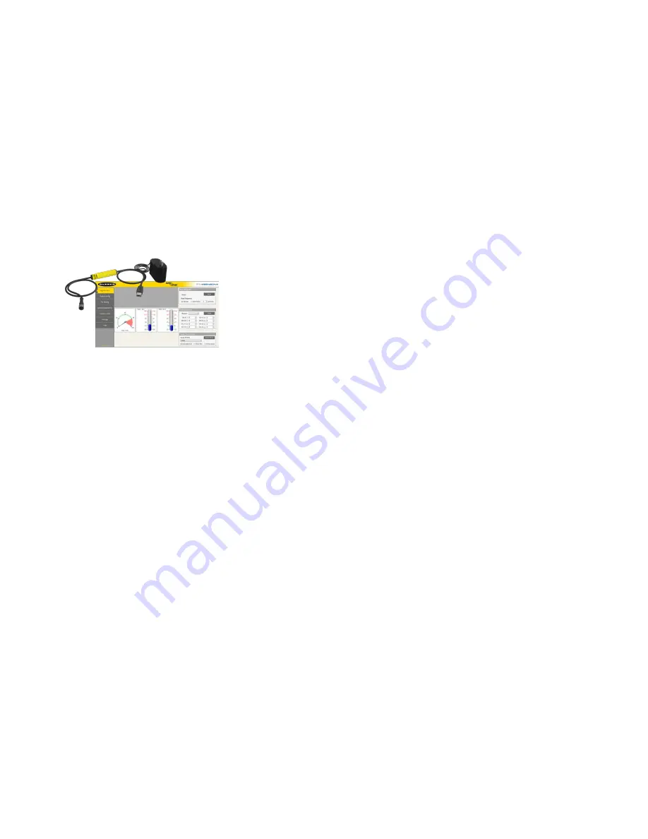
SureCross User Configuration Tool
The User Configuration Tool (UCT) offers an easy way to link I/O points in your wire-
less network, view I/O register values graphically, and set system communication pa-
rameters when a host system is not part of the wireless network.
The UCT requires a special USB to RS-485 (model number BWA-UCT-900 for 1 Watt
radios, BWA-HW-006 can be used for all other radios) converter cable to pass infor-
mation between your computer and the Gateway. Download the most recent revi-
sions of the UCT software from Banner Engineering's website:
Setting Up Your Wireless Network
To set up and install your wireless network, follow these steps:
1. Configure the DIP switches of all devices.
2. Connect the sensors to the SureCross devices.
3. Apply power to all devices.
4. Form the wireless network by binding the Nodes to the Gateway. If the binding instructions are not included in the datasheet, refer to
the product manual for binding instructions.
5. Observe the LED behavior to verify the devices are communicating with each other.
6. Conduct a site survey between the Gateway and Nodes. If the site survey instructions are not included in this datasheet, refer to the
product manual for detailed site survey instructions.
7. Install your wireless sensor network components. If installation instructions are not included in this datasheet, refer to the product
manual for detailed installation instructions.
For additional information, including installation and setup, weatherproofing, device menu maps, troubleshooting, and a list of accesso-
ries, refer to one of the following product manuals.
• SureCross Quick Start Guide: Banner part number
• SureCross Wireless I/O Network Manual:
• Web Configurator Manual (used with "Pro" and DX83 models):
Configuring the DIP Switches
Before making any changes to the DIP switch positions, disconnect the power. DIP switch changes will not be recognized if power isn't
cycled to the device.
For parameters not set via DIP switches, use the User Configuration Tool (UCT) to make configuration changes. For parameters set
using the DIP switches, the DIP switch positions override any changes made using the User Configuration Tool.
Accessing the Internal DIP Switches
To access the internal DIP switches, follow these steps:
SureCross DX80 Gateway
2
www.bannerengineering.com - tel: 763-544-3164
P/N 136325 Rev. F


