background image


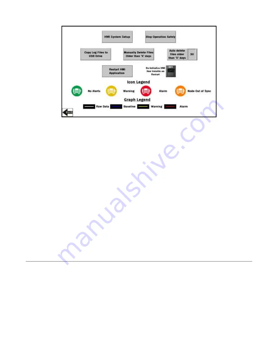
Auto Delete Files Older than ‘X’ Days

The HMI auto deletes files older than the selected number of days.
Default is 30 days with a maximum of 45 days for MulitHop radio kits and 60 days for Performance radio kits.

Copy Log Files to USB Drive

Plug a USB drive into the back of the HMI and click here to select the log files or folders to copy.

HMI System Setup

Enters HMI Panel Setup.
Use for setting Time, Date, and Advanced Options. Entering this screen will clear any logged data from the graphs but will

not clear any data saved to files.

Manually Delete Files Older than ‘X’ Days

Deletes files older than a specified number of days immediately.
Use this option if the HMI is warning about an inability to save data or a lack of storage space. Shortening the auto delete

days parameter may be necessary.

Re-Initialize HMI Non Volatile on Restart

Flip the switch to ON before restarting the HMI to reinitialize default settings and labels.

Restart HMI Application

Restarts the HMI application, which clears all graphed data but retains the saved logs.

Stop Operation Safely

Stops HMI operation safely without data corruption before you power off the HMI.

Always use this button before powering down to avoid data file corruption.

 If a 

Failed to write logged data to file

 or

Failed to save

 message appears, this is because of a power loss during the saving process. You must delete this file (from

the day of the power loss) by using the HMI System Setup menu.

Advanced Options

Install a Warning or Alarm Light

Add a tower light or indicator light (such as a K70, TL50, TL70, etc.) to the solution box for added local indications of all clear,

warnings, or alarms.
The DXM Controller uses PNP outputs with a maximum of 100 mA per output. An interposing relay may need to be added to

accommodate higher amperage lights.

1. Cut a hole in the box and mount the light accordingly.
2. Wire the DC ground to the light or an interposing relay from the bottom row of the gray two-row terminal blocks inside the

Solutions Kit on the DIN rail adjacent to the DXM Controller.

3. Wire the input of the light or interposing relay to the DXM.

a) O1 – Pin 5 – indicates a radio/asset in an Alarm condition

b) O2 – Pin 6 – indicates a radio/asset in a Warning condition

c) O3 – Pin 7 – indicates a radio/asset in either a Warning or an Alarm condition

d) O4 – Pin 8 – indicates no Warning or Alarm conditions exist


Vibration Monitoring and Predictive Maintenance Solutions Kit Quick Start Guide (MultiHop)

8

www.bannerengineering.com - Tel: + 1 888 373 6767

P/N 214301 Rev. F

Summary of Contents for SolutionsKit9-Vibe-MH

Page 1: ...R4 Wireless Controller 5 port Ethernet switch 14 x 12 Polycarbonate enclosure DIN rails and terminal blocks M12 power input connector SolutionsKit9 Vibemetric MH 900 MHz Metric SolutionsKit2 Vibe MH 2...

Page 2: ...odbus Sensor ID value from 11 to 50 Use the left button to cycle the value from 0 to 9 and the right button to accept the value and move the cursor to the next digit right 6 Push and hold button 2 The...

Page 3: ...are needed for the system Note that entering binding mode causes all radios to go out of sync with the DXM until after the DXM exits binding mode The radios will resume communicating with the DXM wit...

Page 4: ...es when that Node is baselining Only temperature warnings and alarms appear during the baselining phase After baselining is complete the threshold levels are established and vibration alerts may begin...

Page 5: ...hold for five samples in a row or the user setting on the Settings screen and Chronic alerts are when a 100 point moving average crosses the thresholds Only data from an operational asset is used to c...

Page 6: ...etwork via Ethernet or a separately sold cellular modem DO NOT set the cloud push interval in the XML file because the script triggers the push Enable Password for Settings Lvl 8 Turn ON OFF the switc...

Page 7: ...box in any of the New Settings rows to manually enter a new value for any or all the warning or alarm thresholds including temperature 5 Set vibration settings back to zero to use the original baselin...

Page 8: ...use this button before powering down to avoid data file corruption If a Failed to write logged data to file or Failed to save message appears this is because of a power loss during the saving process...

Page 9: ...ical Note p n b_4510565 on the Vibration and Temperature sensor Web page Only the default configuration of 1x 2x 3 10x is available on the Solutions Kit Table 2 Spectral band floating point registers...

Page 10: ...less Controller can connect to the Web via Ethernet or an internal cell module The controller pushes data from the DXM to be stored and displayed on a website The Banner platform for storing and monit...

Page 11: ...ownload the existing configuration file from your DXM to your hard drive 1 On the computer download the DXM Configuration Software v4 from the Banner Engineering website and install it 2 On the DXM Ap...

Page 12: ...ebpage into the Site ID field Save and Upload the Configuration File After making any changes to the configuration you must save the configuration files to your computer then upload it to the device C...

Page 13: ...r PC b_4492805 This creates continuity between the site created on the website with the DXM If the DXM has network connection it will upload data on its next cloud push interval Refer to the Banner CD...

Page 14: ...F DXM LCD 20 C to 80 C 4 F to 176 F Micro SD Card if applicable 25 C to 85 C 13 F to 185 F 90 maximum relative humidity non condensing Certification Banner Engineering Europe Park Lane Culliganlaan 2...

Page 15: ...t conomique Canada L exploitation est autoris e aux deux conditions suivantes 1 L appareil ne doit pas produire de brouillage 2 L utilisateur de l appareil doit accepter tout brouillage radio lectriqu...

Reviews: