Banner Q5XKLAF2000-Q8 Instruction Manual Download Page 12

Note: The number that follows trc on the display indicates which channel is selected.
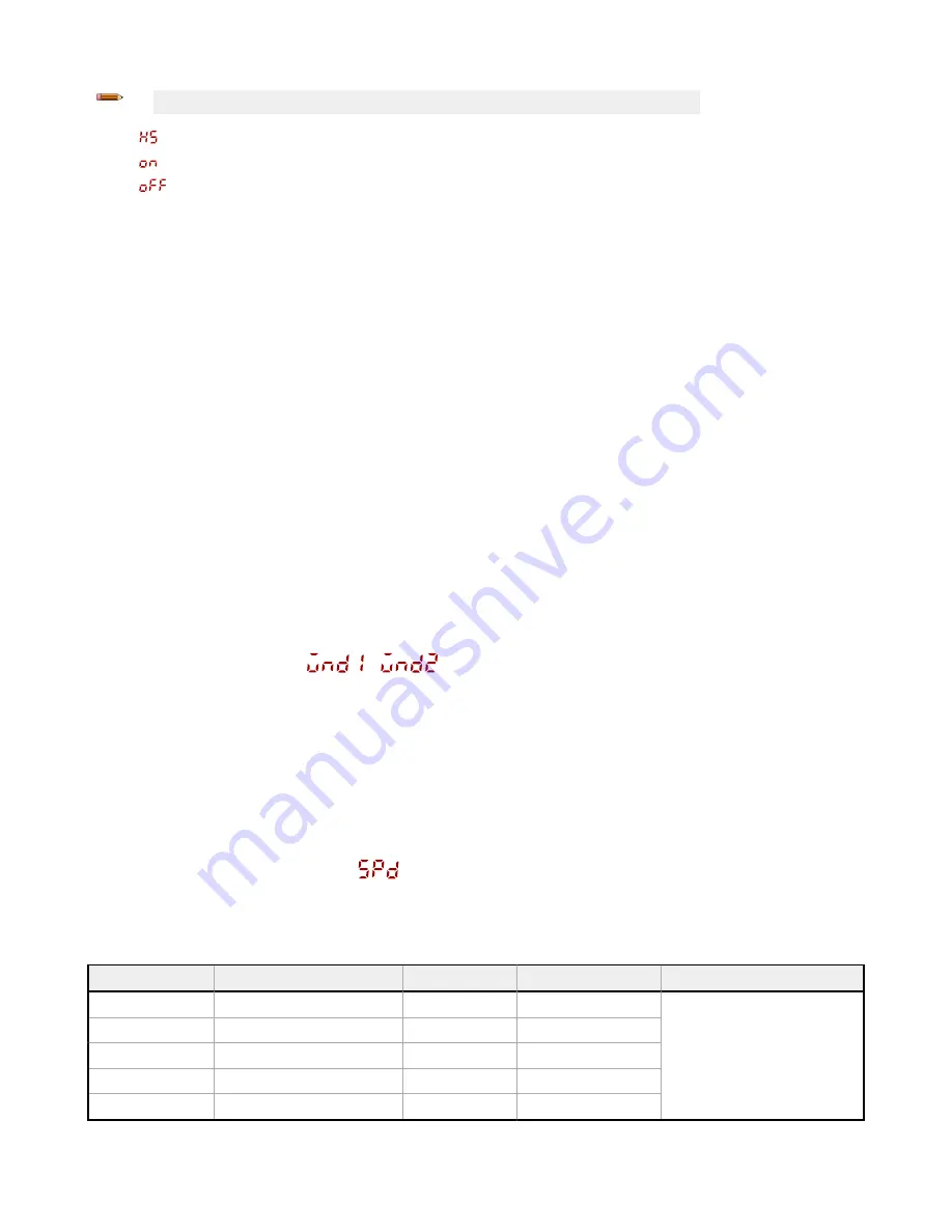
—High-Speed Adaptive Tracking On

—Adaptive Tracking On

—Adaptive Tracking Off (default)

OFF disables the Adaptive Tracking Algorithm—Prevents the sensor from adjusting the thresholds around the taught

reference surface while the sensor is in dual mode. The sensor will not adapt to or learn any target. Environmental changes

may cause the displayed value to deviate from 100P (100%) over time. A periodic re-teach of the reference surface may be

required to restore the displayed value to 100P if this is important to the application.
There are some cases in which disabling adaptive tracking is useful. For example, disable adaptive tracking if the target

passes very slowly through the sensing beam, if the target might stop while partially blocking the beam, and if the

environmental conditions are stable.
ON enables the Adaptive Tracking Algorithm at the standard speed—Recommended for many applications detecting low

contrast targets. Standard adaptive tracking adjusts the thresholds around slowly changing background and environmental

conditions. It adjusts the sensor for stable detection when the environment changes due to gradual dust accumulation,

machine vibration, or ambient temperature changes which influence the signal from the reference surface. Standard

adaptive tracking will not easily adapt to or learn slow moving, low contrast targets (for example, clear targets entering and

exiting the beam over approximately 2 seconds).
HS enables the Adaptive Tracking Algorithm at high speed—Optional adaptive tracking setting used with dual mode. Use

high speed adaptive tracking when the signal from the reference surface changes quickly due to unstable environmental

conditions and high contrast and high-speed targets are being detected. High speed adaptive tracking adjusts the sensor

for stable detection in challenging environmental conditions such as dust accumulation, machine vibration, ambient

temperature changes, or a non-stable reference surface (for example, a running belt or web which influences the signal from

the reference surface). For example, if the signal from the reference surface changes by 10% due to environmental effects,

high speed adaptive tracking adjusts the displayed value back to 100P (100%) over 2 to 3 seconds.
High speed adaptive tracking addresses certain applications where the reference surface is not stable, but the sensor must

detect high speed and high contrast targets reliably. With high speed adaptive tracking there is the potential for the sensor

to adapt the thresholds to slow moving or low contrast targets, leading to missed detection events. If the detection events

are generating small signal changes of similar magnitude to the background changes, detection problems are likely.

Stabilize the reference surface to avoid this problem.

3.2.4 Window Size 


Use this menu to manually set a window size for subsequent TEACH operations. This menu is available only if one-point

window (foreground suppression) mode is selected. The default selection is Auto, where the foreground suppression (FGS)

window size is automatically calculated.
This setting is automatically applied during any subsequent teach operation. The window size value represents a ±cm value,

so the total window size is twice this value. For example, a window set of 10 cm gives a 20 cm window centered around the

taught point. The window size can also be changed directly from Run mode after changing the setting to any value except

Auto. For Channel 2, the output must be set to light operate or dark operate.
Values: 0.1 cm to 191 cm

3.2.5 Response Speed 

—2000 mm Models

Use this menu to select the response speed.
Default: 25 milliseconds

Table 1: Tradeoffs

Response Speed

Response Speed in Sync Mode

Repeatability

Ambient Light Rejection Excess Gain

3 ms

6 ms

1000 µs

Disabled

See Excess Gain in 

Specifications

 on

page 30

5 ms

10 ms

1600 µs

Enabled

15 ms

30 ms

3 ms

Enabled

25 ms

50 ms

5 ms

Enabled

50 ms

100 ms

10 ms

Enabled

Q5X Laser Triangulation Sensor with Background Suppression


12

www.bannerengineering.com - Tel: +1.763.544.3164


Summary of Contents for Q5XKLAF2000-Q8

Page 1: ...Q5X Laser Triangulation Sensor with Background Suppression Instruction Manual Original Instructions 208794 Rev A 6 November 2018 Banner Engineering Corp All rights reserved 208794...

Page 2: ...anual Adjustments 18 3 4 Remote Input 18 3 4 1 Select the TEACH Mode Using the Remote Input 19 3 4 2 Reset to Factory Defaults Using the Remote Input 20 3 5 Locking and Unlocking the Sensor Buttons 20...

Page 3: ...annel 1 Default Channel 2 Default Connection Q5XKLAF2000 Q8 95 mm to 2000 mm 9 5 cm to 200 cm IO Link Push pull output User selectable to be fixed NPN or PNP PNP output or user selectable multi functi...

Page 4: ...afety Notes Low power lasers are by definition incapable of causing eye injury within the duration of a blink aversion response of 0 25 seconds They also must emit only visible wavelengths 400 to 700...

Page 5: ...tons Use the sensor buttons SELECT TEACH CH1 CH2 and MODE to program the sensor SELECT TEACH Press to select menu items in Setup mode Press and hold for longer than 2 seconds to start the currently se...

Page 6: ...y a wall C C Incorrect Correct Figure 5 Orientation for a moving object C C Incorrect Correct Figure 6 Orientation for a height difference Horizontal Orientation Vertical Orientation Optimal C C Figur...

Page 7: ...Load Load Figure 12 Channel 1 PNP Output Channel 2 PNP Output NPN Output and Remote Input 4 1 3 2 10 30V dc CH1 CH2 Load Remote Input Figure 13 Channel 1 NPN Output Channel 2 NPN Remote Input PNP Outp...

Page 8: ...ote If neither SELECT nor CH1 CH2 are pressed after step 2 the new selection flashes slowly for a few seconds then flashes quickly and the sensor automatically changes the Channel and returns to Run m...

Page 9: ...e menu is available when Teach CH1 is set to FGS Adaptive Tracking menu is available when Teach CH1 is set to Dual Mode high excess gain mode standard excess gain with increased noise immunity Gain an...

Page 10: ...on when pulled high set Remote Teach input master slave pulse sec range set Delay Timer value seconds have decimal to ms Menu not present when is set to and default to 0 defaults to 1 or 10 depending...

Page 11: ...n One point background suppression Dual intensity distance window After the TEACH mode is selected from Run mode press and hold TEACH for longer than 2 seconds to start the TEACH mode and program the...

Page 12: ...tion machine vibration ambient temperature changes or a non stable reference surface for example a running belt or web which influences the signal from the reference surface For example if the signal...

Page 13: ...cted No delay Delay enables the selection of on and off delay timers One shot enables a one shot fixed output pulse duration Totalizer enables an output after a defined number of targets are counted O...

Page 14: ...ude the decimal point values in seconds include the decimal point 1 to 999 ms when or is selected the 1 to 9 ms range is available for 1 5 2 3 and 5 ms response times 1 0 to 90 0 s From Run mode press...

Page 15: ...ion Use this menu to select the zero reference location Changing the zero reference location only affects the readout on the display and does not affect the output The default is 0 the front of the se...

Page 16: ...tings 3 2 11 Offset Use this menu to set an offset from the taught surface during a TEACH procedure This menu is available only if one point window foreground suppression mode or one point background...

Page 17: ...ntimeter with a decimal point at 60 centimeters inch with a decimal point at 24 inches 3 2 14 Output Type Polarity Use this menu to select the output polarity Default Push Pull IO Link on pin 4 and so...

Page 18: ...s is completed use the manual adjustment to adjust the sensitivity of the thresholds around the taught reference point The taught reference point is a combination of the measured distance and returned...

Page 19: ...Lock loc Button Lock 8x Reset to Factory Defaults maintain remote input SET Remote Input Figure 19 Remote Input Map 3 4 1 Select the TEACH Mode Using the Remote Input 1 Access the TEACH selection Acti...

Page 20: ...ed and held When in mode displays when MODE is pressed and held To access the manual adjust options briefly press and release CH1 CH2 or MODE To enter TEACH mode press the SELECT TEACH button and hold...

Page 21: ...ensor must be set to to use the following instructions Note To program the sensor using remote input remote input must be enabled 1 Present the target Method Action Result Push Button Present the firs...

Page 22: ...t distance by the horizontal minimum object separation and the switch point distance flash alternately on the display One valid distance with one invalid TEACH point Sets a switch point between the on...

Page 23: ...od Action Result Push Button Press TEACH to stop teaching the sensor The new switch point flashes rapidly and the sensor returns to Run mode Remote Input Single pulse the remote input T Table 3 Expect...

Page 24: ...verification is not desired Note The sensor must be set to to use the following instructions The FGS indicator is amber to indicate One Point Window Foreground Suppression mode Note To program the sen...

Page 25: ...point that after the offset results in a both switch points outside of the range Sets a window two switch points centered around 150 cm The window size is 7 5 cm and the window center point distance...

Page 26: ...hes on the display One invalid TEACH point Sets a switch point at 120 cm and the switch point distance flash alternately on the display One valid TEACH point that after offset becomes invalid Sets a s...

Page 27: ...the sensing range Sets a dual intensity distance window centered around the taught reference surface that is outside the sensing range The sensing conditions may not be as reliable flashes on the disp...

Page 28: ...he master sensor and slave sensor must share a common power source 1 Configure the first sensor as the master navigate 2 Configure the second sensor as the slave navigate 3 Connect the white wires of...

Page 29: ...Link AOIs The job of a Process Data AOI is to intelligently parse out the Process Data word s in separate pieces of information All that is required to make use of this AOI is an EtherNet IP connectio...

Page 30: ...nect Construction Housing ABS Lens cover PMMA acrylic Lightpipe and display window polycarbonate Temperature Effect Typical 0 5 mm C at 500 mm 1 0 mm C at 1000 mm 2 0 mm C at 2000 mm Discrete Output D...

Page 31: ...Shock MIL STD 202G Method 213B Condition I 100G 6x along X Y and Z axes 18 shocks with sensor operating Operating Conditions 10 C to 50 C 14 F to 122 F 35 to 95 relative humidity Storage Temperature...

Page 32: ...5 1 Dimensions All measurements are listed in millimeters inches unless noted otherwise Q5X Laser Triangulation Sensor with Background Suppression 32 www bannerengineering com Tel 1 763 544 3164...

Page 33: ...0 70 80 0 200 400 600 800 1000 1200 1400 1600 1800 2000 Matte targets with uniform reflectivity 6 to 90 Matte targets with a non uniform reflectivity 6 to 90 Figure 24 Minimum Object Separation Distan...

Page 34: ...ty of taught reference Distance mm Change in Intensity 0 10 20 30 40 50 60 70 80 90 100 110 120 0 25 50 75 100 125 150 175 200 225 250 275 300 Output switches with intensity change Intensity of taught...

Page 35: ...e to the taught reference point The user adjustable switch point defines the sensitivity and the output switches when the match percentage to the reference point crosses the switch point Your specific...

Page 36: ...ble describes the abbreviations used on the sensor display and in this manual Abbreviation Description No valid signal in range The sensor has not been taught One shot First Multiple light reflections...

Page 37: ...er on Lock locked Laser off Master Near zero reference location the front of the sensor is 0 and the measurement increase as the target moves further away from the sensor Object Off delay timer Channe...

Page 38: ...de Start Stop TEACH process selection Channel 1 Channel 2 Totalizer Total counts Unlock unlocked Unit Saturated signal too much light Window size Channel 1 Channel 2 Yes Zero select the zero reference...

Page 39: ...or increase the angle of incidence between the sensor and the target EEPROM fault Contact Banner Engineering to resolve Laser fault Contact Banner Engineering to resolve Output short circuited Check...

Page 40: ...sy sensor mounting to extruded rail T slots Metric and inch size bolts available Side mounting of some sensors with the 3 mm screws included with the sensor 37 50 56 3 8 16 UNC X 4 in 3X M3X0 5 3X M4X...

Page 41: ...0 7 ISO 6H TAP THRU SMBQ5XM4F Fixing plates for mounting to back of sensor Stainless steel plates Customer supplied mounting plate thickness minimum 2 mm maximum 4 mm with screws included in kit M4 X...

Page 42: ...er Engineering de Mexico Monterrey Head Office Edificio VAO Av David Alfaro Siqueiros No 103 Col Valle Oriente C P 66269 San Pedro Garza Garcia Nuevo Leon Mexico Phone 52 81 8363 2714 or 01 800 BANNER...

Page 43: ...No 308 Section 1 Neihu Road Taipei 114 Taiwan Phone 886 0 2 8751 9966 Website www bannerengineering com Email info bannerengineering com tw Q5X Laser Triangulation Sensor with Background Suppression w...

Page 44: ...ECIAL DAMAGES RESULTING FROM ANY PRODUCT DEFECT OR FROM THE USE OR INABILITY TO USE THE PRODUCT WHETHER ARISING IN CONTRACT OR WARRANTY STATUTE TORT STRICT LIABILITY NEGLIGENCE OR OTHERWISE Banner Eng...

Reviews: