background image

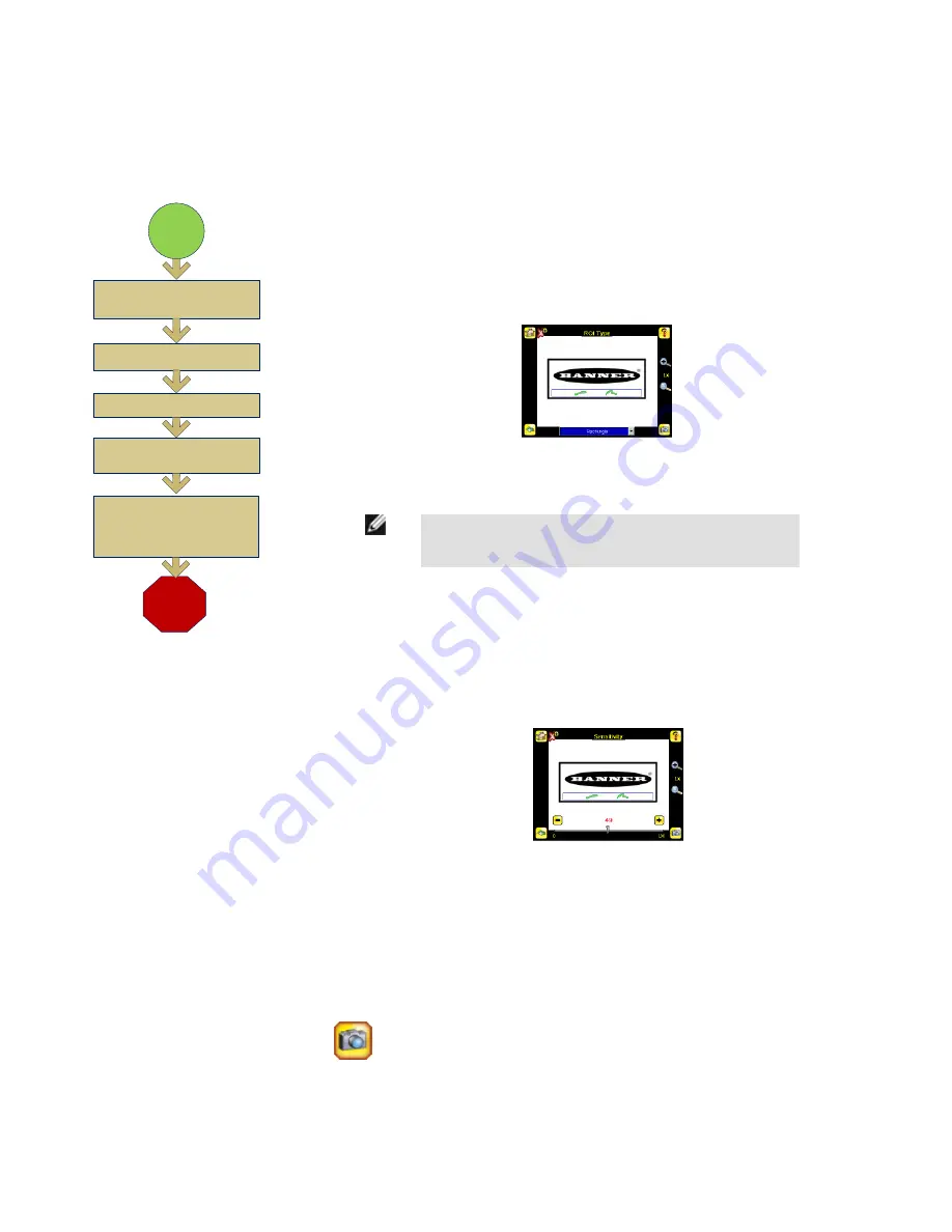
Configuring a Blemish Sensor


Finish

Set Pass Count

Start

Use Manual Trigger to Test 

Range of Good and Bad 

Parts

Select ROI Type and 

Adjust

Adjust Sensitivity

Adjust Edge Length Range


NOTE: Make sure you test a range
of samples checking that the
"worst" good part passes, and the
"best" bad part fails.

The flow chart at left provides an overview of the steps to setting up an inspection on the iVu TG
sensor as a Blemish sensor.

1. Make sure you have a good part to use for the inspection setup. Normally, the part being

inspected is centered in the field of view with the feature of interest surrounded by the Re-
gion of Interest (ROI), the blue rectangle. The ROI can be rotated and resized, and is red
when selected for adjustment.


2. Adjust the ROI so that the part is within the ROI. The pattern will be highlighted in green.

NOTE: When running a Blemish inspection, the sensor will only
find edges within the ROI.

3. Configure the following parameters:

• Sensitivity: Sensitivity is used to fine-tune how sensitive the sensor is to finding blem-

ishes or other edges within the ROI. The Sensitivity value helps account for light varia-
tions that might affect how well the sensor detects edges. The Sensitivity scale is from 0
to 100 where 0 means least sensitive and 100 means most sensitive. If set near 0, the
sensor will find very sharp edges with strong contrast; if set near 100, the sensor will find
very dim or blurry edges, and may be unstable.


• The Edge Length Range: The sensor counts all the edge pixels it detects in the ROI.

The bar at the bottom of the Edge Length Range screen shows all the different contigu-
ous edge segments found. Edge segments within the two brackets [ ] are highlighted in
green and those outside the brackets are ignored and colored yellow. You can move
each bracket to add or remove more of the edge segments from consideration.

• Pass Count: The sensor aggregates all the edge pixels that fall within the Edge Length

Range and indicates the value with a small colored bar at the bottom of the page. If with-
in the range brackets, the bar is green, otherwise it is yellow.

4.

 Use the Manual Trigger, located in the lower-right corner of the screen, to test good

and bad parts. Adjust settings as necessary and retest.


iVu TG Quick Start Guide

12

www.bannerengineering.com - tel: 763-544-3164

Rev. C

Summary of Contents for iVu TG

Page 1: ...iVu TG Quick Start Guide Rev C 10 3 2011 143367...

Page 2: ...with Integrated Display 5 Cable Connections for the iVu TG with a Remote Display 5 Demo Mode 7 Sensor Types 7 Selecting a Sensor Type 7 Acquiring a Good Image 8 Configuring an Area Sensor 11 Configur...

Page 3: ...entation is available on the Product CD Datasheets iVu TG Datasheet iVu TG Remote Display iVu Series Remote Display Datasheet Other iVu TG Sensor Reference iVu TG Communications Guide iVu TG User s Ma...

Page 4: ...allow the sensor to be mounted either perpendicular to the part or at an adjustable angle Available iVu Brackets SMBIVURAL SMBIVURAR SMBIVUU Thread three M4 x 4mm screws through the bracket into the m...

Page 5: ...een Output 2 Output NOTE Microlens models show C Mount model connections are identical Cable Connections for the iVu TG with a Remote Display The cable connections on the iVu sensor are shown below an...

Page 6: ...External Trigger Input 5 Gray Remote Teach Input 1 White Output 1 Output 8 Red Ready Output 4 Yellow Strobe Out 5V dc only Output 3 Green Output 2 Output 9 Orange Not used N A 10 Light Blue Not used N...

Page 7: ...s normal operating mode with default settings NOTE You may return to Demo Mode any time by going to Main Menu System Sensor Type and select ing Demo Mode Sensor Types The iVu TG sensor includes three...

Page 8: ...background Depending on the target this may mean the integral ring light is not the best choice and other Banner lights should be consid ered Adjust the mounting angle to provide the clearest image o...

Page 9: ...il the Focus Number peaks NOTE Turning the Focusing Window counter clockwise focuses on closer objects while turning the Focusing Window clockwise focuses on more distant objects 3 Once the best image...

Page 10: ...the focus until the Focus Number peaks 3 Replace the Lens Enclosure on the camera C Mount Models D C A B E C A C Mount Lens B Lens Enclosure C Retainer Ring optional D Filter optional E Filter Retain...

Page 11: ...ok for To set the Intensity Range use the eye dropper on the left of the screen to select the target feature then use the slider bar at the bottom of the display to fine tune the selection As the slid...

Page 12: ...ges within the ROI The Sensitivity value helps account for light varia tions that might affect how well the sensor detects edges The Sensitivity scale is from 0 to 100 where 0 means least sensitive an...

Page 13: ...he reference part or label The Percent Match scale is from 0 to 100 where 0 is the most tolerant and 100 is the least tolerant Move the slider to the left or to the right to adjust the setting For the...

Page 14: ...ary edge and the second edge moves and rotates in relation to this primary edge The primary edge is identified by a small O as shown below Sensitivity is used to fine tune how accurately the sensor de...

Reviews: