background image

 Software-specific information

 Power Panel C50 User's manual V1.10 

55

6.3.3 User agent

For identification purposes, each web browser transmits various information (e.g. browser name, version, operating

system) to the web server providing the HTML page.
As part of the HTTP header, a web browser identifies itself as a user agent. The web browser transmits additional

information with the HTTP header:

Example:

User-Agent: Mozilla/5.0 ... 

BRPanel/1.0 (PPT50;landscape;1280x800;6PPT50.101E-16B;)

Description of the Power Panel information:

Identification := BRPanel/<Version> (<Type>;<Orientation>;<Resolution>;<OrderId>)

BRPanel

Identification as B&R panel.

<Version>

Version number of the comment (expression in parentheses), which is primarily used to evaluate the information within the paren-

theses correctly.

Format of <Version>:


<Number>.<Number>

<Type>

Name of device family: 

PPT50

PPC50

, etc.

The orientation of the screen display contains one of the following two values:

landscape

Landscape

<Orientation>

portrait

Portrait

Resolution of the device in the format "WIDTHxHEIGHT".

Format of <Resolution>:


WIDTHxHEIGHT

WIDTH

Width of the display in pixels.

HEIGHT

Height of the display in pixels.

<Resolution>

The width and height of the display are output according to the orientation:

Example for landscape format: 

1280x800

Example for portrait format: 

800x1280

<OrderId>

Model number of the Power Panel.

6.3.4 Using the developer tools

The developer tools make it possible to access the browser from any remote computer over the network. Developer

tools can help to edit pages on the fly and quickly diagnose problems.

Information:

To be able to use the developer tools, either 

Google Chrome

 or the 

Chromium

 is required.

Information about the functionality and use of the developer tools: 

Chrome DevTools

Enabling remote developer tools:

1. Enable parameter Developer tools in the terminal configuration.
2. Set a valid and free port (Port number).
3. In Automation Studio, compile the project and transfer it to the Power Panel C50.

The web browser is started with the corresponding settings and enabled developer tools.

To use the remote developer tools, the following conditions must additionally be met:

The Power Panel is accessible via the Ethernet network.

The network and the computer used permit communication.

A browser that supports the developer tools is required on the remote computer.

Launching the developer tools

If the developer tools are enabled and the web browser is started, the remote computer can launch the developer

tools for the Power Panel browser with the following URL:

With the IP address of the Power Panel: 

http://IP address:Port

IP address

IP address of the terminal.

If DNS is enabled and a hostname is specified for the terminal, the IP address of the terminal can be determined using appropriate

network tools (e.g. nslookup).

Port

The port was configured in the corresponding parameter (default setting: 9222).

Summary of Contents for 4PPC50.0702-10A

Page 1: ...ut prior notice B R Industrial Automation GmbH is not liable for technical editorial errors or incomplete information in this manual In addition B R Industrial Automation GmbH shall not be liable for...

Page 2: ...1557771373112 1 10 2020 05 07...

Page 3: ...nt of delivery 15 4 2 2 Required accessories 15 4 2 3 Optional accessories 15 4 3 System architecture 16 4 4 Technical information 17 4 4 1 System requirements 17 4 4 2 Data and real time clock buffer...

Page 4: ...6 1 3 Screen 51 6 1 4 Audio 51 6 1 5 Web 52 6 1 6 Update 52 6 2 Network information 53 6 2 1 MAC addresses 53 6 3 Web browser information 54 6 3 1 Supported fonts 54 6 3 2 Supported video formats 54 6...

Page 5: ...directives and standards CE 65 9 2 1 Overview of standards 66 9 2 2 Requirements for immunity to disturbances 67 9 2 3 Emission requirements 69 9 2 4 Mechanical conditions 70 9 2 5 Electrical safety...

Page 6: ...r system provider 1 2 1 Organization of notices Safety notices Contain only information that warns of dangerous functions or situations Signal word Description Danger Failure to observe these safety g...

Page 7: ...lly stringent safety precautions In particular this includes the use of these systems to monitor nuclear reactions in nuclear power plants flight control systems air traffic control the control of mas...

Page 8: ...trical assemblies are installed must be grounded Assemblies are only permitted to be touched on the narrow sides or front plate Always place assemblies on suitable surfaces ESD packaging conductive fo...

Page 9: ...must be kept closed during operation 2 6 2 Ambient conditions Dust moisture aggressive gases The use of operating and monitoring devices e g industrial PCs Power Panels Mobile Panels etc and unin terr...

Page 10: ...urity measures include for example Segmentation of the network e g separation of the IT network from the control network1 Use of firewalls Use of authentication mechanisms Encryption of data Use of an...

Page 11: ...t USB and X2X Link interfaces De pending on the version the CAN RS232 and or RS485 fieldbus interfaces are also available User friendly The multi touch panel is available with a clear or anti glare gl...

Page 12: ...9 1 GB DRAM Display and touch screen 7 0 800 x 480 WVGA resolution projected capacitive touch screen multi touch support anti glare glass front with black frame landscape and portrait format configura...

Page 13: ...l number Format Resolution Landscape Portrait format Resolution WVGA 800 x 480 WXGA 1280 x 800 WXGA 1280 x 800 HD 1366 x 768 0702 101E 121E 156B Model number 4PPC50 xxxx xxx Front Black Glass Glass an...

Page 14: ...6H CAN bus RS232 4PPC50 101E 13A 10 1 Glass chemically hardened 6H anti glare CAN bus RS485 4PPC50 101E 13B 10 1 Glass chemically hardened 6H CAN bus RS485 4PPC50 121E 10A 12 1 Glass chemically harden...

Page 15: ...1 Model number Description 0TB6102 2110 01 Accessory terminal block 2 pin 3 81 cage clamp terminal block 1 5 mm 0TB5104 2110 01 Accessory terminal block 4 pin 2 5 cage clamp terminal block 0 5 mm 0TB5...

Page 16: ...ol tasks A mapp View server configured with Automation Studio can pro vide the HMI application The web browser integrated in the terminal handles the display of the HMI application e g mapp View on th...

Page 17: ...ferroelectrically Unlike normal SRAM this does not require a battery Real time clock Gold foil capacitor The real time clock is buffered for approx 1000 hours by a gold foil capacitor The gold foil ca...

Page 18: ...tem perature see Temperature specifications in the Technical data section must be taken into account Depending on the display size derating must be taken into account under the following conditions S...

Page 19: ...ddition to this derating a further derating must be observed depending on the installation condi tions see Derating the ambient temperature on page 18 4 4 7 Surface resistance Chemical resistance of t...

Page 20: ...struction cycle time 0 01 s Application memory Type 2 GB eMMC flash memory Data retention 10 years Writable data amount Guaranteed 40 TB Results for 5 years 21 9 GB day Guaranteed erase write cycles 2...

Page 21: ...orientation Vertical Tilt 25 Rotation In 90 increments portrait landscape Installation elevation above sea level 0 to 2000 m No limitation 2000 m Reduction of ambient temperature by 0 5 C per 100 m D...

Page 22: ...cal Direction U Direc tion D Typ 60 Direction U Direc tion D Typ 85 U direction Typ 80 D direction Typ 65 Direction U Direc tion D Typ 85 Backlight Type LED Brightness Typ 500 cd m Typ 400 cd m Half b...

Page 23: ...er rate 1 Bus length 25 m 1 Mbit s Bus length 60 m 500 kbit s Bus length 200 m 250 kbit s Bus length 1000 m 50 kbit s 1 In addition to the bus length the maximum achievable transfer rate also depends...

Page 24: ...85 90 95 100 RH 1 2 Diagram legend 1 Operation T C Temperature in C 2 Storage and transport RH Relative humidity RH in percent and non condensing 4 6 2 10 1 variants 80 70 60 50 40 30 20 10 0 10 20 30...

Page 25: ...2 Diagram legend 1 Operation T C Temperature in C 2 Storage and transport RH Relative humidity RH in percent and non condensing 4 6 4 15 6 variants 80 70 60 50 40 30 20 10 0 10 20 30 40 50 60 70 80 9...

Page 26: ...197 6x 11 36 5 5 7 128 201 6 2x 147 4 144 6 View A View A 1 6x 8 9 4 x R 3 5 140 2 1 6x retaining clips with torque limiting 2 Anodized front plate E6 C8 black Dimensions of the installation cutout fo...

Page 27: ...271 5 190 4x R3 5 8x 11 174 36 5 5 7 2x 176 2x 100 View A View A 1 2 1 8x retaining clips with torque limiting 2 Anodized front plate E6 C8 black Dimensions of the installation cutout for this Power P...

Page 28: ...A View A 38 5 7 208 5 97 117 324 311 1 221 5 308 752 4x R3 5 2 1 8x retaining clips with torque limiting 2 Anodized front plate E6 C8 black Dimensions of the installation cutout for this Power Panel...

Page 29: ...55 401 414 38 5 7 245 5 54 05 View A View A 1 258 5 395 725 4x R3 5 2 1 9x retaining clips with torque limiting 2 Anodized front plate E6 C8 black Dimensions of the installation cutout for this Power...

Page 30: ...date Green Blinking Mode BOOT system startup On Mode SERVICE or overtemperature shutdown R E Red Blinking If LED R E blinks red and LED RDY F blinks yellow a license violation has occurred On Mode SER...

Page 31: ...NOT_ACTIVE The interface is either in mode NOT_ACTIVE or one of the following modes or errors is present The device is switched off The LED status indicator is disabled The device is in the startup p...

Page 32: ...lights up in this mode this means that the MN has failed Off Mode READY_TO_OPERATE The interface is in mode READY_TO_OPERATE Managing node MN Cyclic and asynchronous communication Received PDO data is...

Page 33: ...Off Terminating resistor not switched on OPS2 Yellow On Terminating resistor switched on OPS3 Yellow On TxD RxD Data is being transmitted or received IF6 CAN bus OPS4 Yellow On TxD RxD Data is being t...

Page 34: ...Automation Studio SERVICEmode default Warm restart Cold restart DIAGNOSISmode Key code 1 Press and hold key 2 s 2 LED R E lights up red and then goes dark 3 As soon as LED R E goes dark the button can...

Page 35: ...Ethernet activity taking place on the bus LNK ACT Green Off No link established to an Ethernet network Transfer rate 8 1 Front touch screen LNK ACT SPEED Back SPEED Orange Green Off Not used Informati...

Page 36: ...linking Link established to an Ethernet network and Ethernet activity taking place on the bus LNK ACT Green Off No link established to an Ethernet network Transfer rate Orange On 1000 Mbit s Green On...

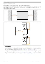
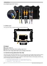
Page 37: ...ces should be handled with extreme care with regard to EMC location of cables etc Notice Possible malfunction of interfaces and touch screen If functional ground is not present faults in interface com...

Page 38: ...ssories 0TB5106 2110 01 Accessory terminal block 6 pin 2 5 cage clamp terminal block 0 5 mm2 1 6 Front touch screen Back A terminating resistor can be switched on individually and independently for ea...

Page 39: ...earth grounding clip on the device and the GND connection of the power supply are con nected internally in the Power Panel Front touch screen Back The pinout for the power supply is listed in the foll...

Page 40: ...ust be taken into account The ventilation holes are not permitted to be covered When installing the device the permissible mounting orientations must be observed The device must be installed such that...

Page 41: ...device into the front of the prepared burr free and flat installation cutout For the dimensions of the installation cutout see section Dimensions for the individual devices 2 Install the retaining cli...

Page 42: ...riants 40 mm 40 mm Air outlet 60 mm 60 mm 45 mm Air intake Information In worst case operation the specified spacing for air circulation applies at the maximum specified ambient temperature see Temper...

Page 43: ...for the respective device Vertical or tilted mounting orientation 25 25 The device can be operated without derating see environmental conditions in the technical data Other mounting orientations hori...

Page 44: ...connected to ground e g grounding rail in the control cabinet using a short path Grounding Securing cables The cables to from the Power Panel are secured as follows depending on the display variant D...

Page 45: ...Required accessories from the content of delivery 1 2 M3x4 screws and 2 accessory plate 1 Attach the accessory plate 2 to the back of the device 2 Secure the accessory plate with the mounting screws 1...

Page 46: ...Power Panel is delivered with Boot AR This is an operating system with a limited range of functions but that provides all functions necessary for an online connection between Automation Studio and th...

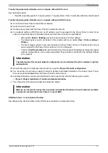
Page 47: ...ower Panel address 0 0 0 0 is displayed Command Set IP parameters Power Panel shortcut menu opens the dialog box where all required network configurations can be made temporarily they should be identi...

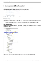
Page 48: ...Configuration in Automation Studio Standard options The standard configuration options for the Power Panel C50 in Automation Studio are described in Automation Help Programming Editors Configuration e...

Page 49: ...ne No boot logo selected Dateiname bmp Boot logo Dateiname bmp selected A static boot logo for the Power Panel can be selected here that will be displayed during device startup and when estab lishing...

Page 50: ...fault setting EMPTY IP address of the default gateway Subnet mask Default setting EMPTY The subnet mask is entered here Information The data required for manual network configuration can be obtained f...

Page 51: ...ngle 6 1 3 1 Screensaver settings If the screensaver is enabled additional parameters are displayed Parameter Setting Description Wait time for screensaver Default setting 15 Unit Minutes If there is...

Page 52: ...the focus see Keyboard on page 56 Input can also be made at any time using a connected USB keyboard Information The virtual keyboard is generated by the terminal s operating system If the web applica...

Page 53: ...arted 3 If a valid Terminal OS image was not found the current system is started Valid PPT image for updating the terminal OS A Terminal OS image in a network or on a USB storage medium is valid if it...

Page 54: ...mapping If the HTML based HMI application mapp View contains fonts that do not exist on the Terminal OS the following system fonts are used as replacements instead Replacement font starting with Termi...

Page 55: ...he Power Panel 6 3 4 Using the developer tools The developer tools make it possible to access the browser from any remote computer over the network Developer tools can help to edit pages on the fly an...

Page 56: ...age The Terminal OS image is a compressed image of the Terminal OS operating system of the terminal The Terminal OS image is a package consisting of the following files File Description PPC50Image img...

Page 57: ...r temperature of the device is monitored continuously by multiple sen sors If the internal temperature of the Power Panel reaches or exceeds the switch off temperature an automatic shutdown occurs OFF...

Page 58: ...display with the touch screen should be cleaned at regular intervals 7 2 Screen burn in on LCD TFT monitors Screen burn in afterimages display memory effect image retention or image persistence occurs...

Page 59: ...K Ethernet connection cable RJ45 to RJ45 3 m X20CA0E61 00500 POWERLINK Ethernet connection cable RJ45 to RJ45 5 m X20CA0E61 00800 POWERLINK Ethernet connection cable RJ45 to RJ45 8 m X20CA0E61 01000 P...

Page 60: ...40 X2X Link attachment cable angled 4 m X67CA0X31 0050 X2X Link attachment cable angled 5 m X67CA0X31 0100 X2X Link attachment cable angled 10 m X67CA0X31 0150 X2X Link attachment cable angled 15 m X6...

Page 61: ...or the complete system applies to the complete system in which this accessory is installed for example The technical data in this manual is current as of its creation publication Subject to change wit...

Page 62: ...may differ from those of the complete system The data specified for the complete system applies to the complete system in which this accessory is installed for example The technical data in this manu...

Page 63: ...n kit for Power Panel T Series and C Series variants 9x retaining clips with torque limiting 1x 2 pin cage clamp ter minal block 1x 2 pin screw clamp terminal block See the ac cessories of the Power P...

Page 64: ...onding documentation This can be located and downloaded by searching for the storage medium s model number at www br automation com 8 6 Cable accessories For technical data and additional information...

Page 65: ...agency on techni cal regulating and metrology Eurasian Eco nomic Union 9 2 EU directives and standards CE CE marking The respective product complies with all applicable EU directives and relevant har...

Page 66: ...t 3 Classification of groups of environmental parameters and their severities Section 3 Stationary use at weather protected locations EN 61000 4 2 Electromagnetic compatibility EMC Part 4 2 Testing an...

Page 67: ...nded Temporary degradation of performance must be self recover able C Loss of functions accepted but no destruction of hardware or software program or data The PLC system shall continue to operate as...

Page 68: ...AM 1 kHz Criteria A 1 Only for connections with a permitted line length greater than 3 m Magnetic fields with electrical frequencies Testing performed per standard EN 61000 4 8 Requirements per stand...

Page 69: ...ues per standard EN 61131 2 Zone B Limit values per standard EN 61000 6 4 150 to 500 kHz 79 dB V quasi peak value 66 dB V average value AC mains connection 150 kHz to 30 MHz 500 kHz to 30 MHz 73 dB V...

Page 70: ...1 octave per minute Vibration sinusoidal Transport packaged Testing performed per stan dard EN 60068 2 6 Requirements per standard EN 60721 3 2 Class 2M1 Requirements per standard EN 60721 3 2 Class...

Page 71: ...e fixed in stallation Pollution degree Requirement per standard EN 61131 2 Explanation per standard EN 60664 1 Pollution degree 2 Only non conductive pollution occurs Occasionally however temporary co...

Page 72: ...alidity Canada USA Standards applied UL 61010 1 Safety requirements for electrical equipment for measurement control and laboratory use Part 1 General requirements UL 61010 2 201 Standard for safety r...

Page 73: ...ormity EAC Products with this mark are tested by an accredited test laboratory and permitted to be imported into the newly established Eurasian Customs Union based on EU conformity Validity Russia Bel...

Page 74: ...ion of materials To ensure that devices can be recycled in an environmentally friendly manner it is necessary to separate out the different materials Component Disposal Programmable logic controllers...

Page 75: ...Publishing information Power Panel C50 User s manual V1 10 75...

Page 76: ...nformation 76 Power Panel C50 User s manual V1 10 Publishing information B R Industrial Automation GmbH B R Strasse 1 5142 Eggelsberg Austria Telephone 43 7748 6586 0 Fax 43 7748 6586 26 office br aut...

Reviews: