
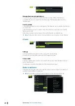
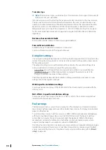
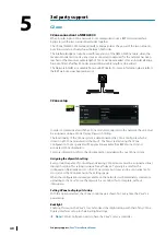
Radar source
In a system with more than one radar sensor, the device to configure is selected from this
menu.
Ú
Note:
Radars that support dual radar mode are represented twice in the source list, with
an A and B suffix.
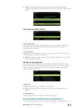
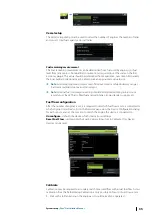
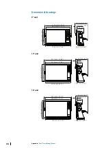
Radar status
Displays scanner information and scanner features, primarily used for information and to
assist with fault finding.
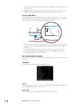
Adjust antenna height
Set the radar scanner height relative to the water surface. The Radar uses this value to
calculate the correct STC settings.
Select antenna length
Select the proper antenna length.
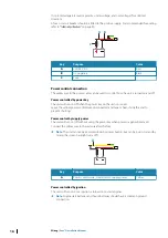
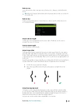
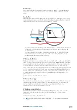
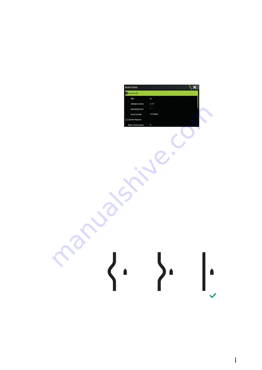
Adjust range offset
The radar sweep should commence at your vessel (a radar range of zero). You may need to
adjust the radar range offset to achieve this. If this is set incorrectly, a large dark circle in the
center of the sweep might occur. You might notice straight objects such as straight sea walls
or piers having curves or an indentation. Objects close to your vessel may appear pulled in or
pushed out.
Adjust the range offset as below when the vessel is about 45 to 90 m (50 to 100 yards) from a
straight-walled jetty or similar feature that produces a straight line echo on the display.
1
Position the vessel in relation to the jetty.
2
Adjust the range offset to make the jetty echo appear as a straight line on the
display.
X
X
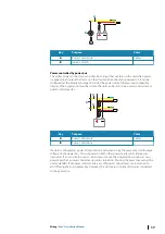
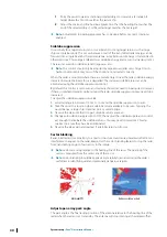
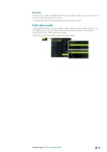
Adjust bearing alignment
This option is used to align the heading marker on the screen with the center line of the
vessel. This will compensate for any slight misalignment of the scanner during installation.
Misalignment that is not corrected for will compromise target tracking and can result in
dangerous misinterpretation of potential navigation hazards.
Any inaccuracy will be evident when using MARPA or chart overlay.
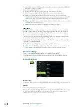
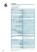
System setup
| Zeus³S Installation Manual
29
Summary of Contents for Zeus3S
Page 1: ...ENGLISH Zeus3 S Installation Manual www bandg com...
Page 2: ......
Page 50: ......
Page 51: ...988 12599 001...