background image

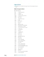
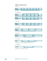
NMEA 0183 supported sentences

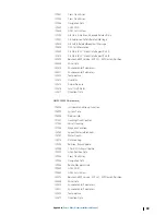
TX / RX - GPS

Receive

GGA

GLL

GSA

GSV

VTG

ZDA

Transmit

GGA

GLL

GSA

GSV

VTG

ZDA

GLC

TX / RX - Navigation

Receive

RMC

Transmit

AAM

APB

BOD

BWC

BWR

Receive
Transmit

RMC

RMB

XTE

XDR

TX / RX - Sonar

Receive

DBT

DPT

MTW

VLW

VHW

Transmit

DBT

DPT

MTW

VLW

VHW

TX / RX - Compass

Receive

HDG

HDT

HDM

Transmit

HDG

TX / RX - Wind

Receive

MWV

MWD

Transmit

MWV

MWD

TX / RX - AIS / DSC

Receive

DSC

DSE

VDM

Ú

Note: 

AIS sentences are not bridged to or from NMEA 2000.

TX / RX - MARPA

Transmit

TLL

TTM

Ú

Note: 

These are only output sentences.

40

Appendix

 | Zeus3 Glass Helm Installation Manual

Summary of Contents for Zeus3 Glass Helm

Page 1: ...ENGLISH Zeus3 GlassHelm Installation Manual www bandg com ...

Page 2: ......

Page 3: ...ate document In case of any queries refer to the brand website of your unit or system www bandg com Compliance Statement This equipment complies with CE under 2014 53 EU Directive The requirements of level 2 devices of the Radio communications Electromagnetic Compatibility standard 2008 Part 15 of the FCC Rules Operation is subject to the following two conditions 1 this device may not cause harmfu...

Page 4: ...t the dealer or an experienced technician for help Countries of intended use in the EU AT Austria BE Belgium BG Bulgaria CY Cyprus CZ Czech Republic DK Denmark EE Estonia FI Finland FR France DE Germany GR Greece HU Hungary IS Iceland IE Ireland IT Italy LV Latvia LI Liechtenstein LT Lithuania LU Luxembourg MT Malta NL Netherlands NO Norway PL Poland PT Portugal RO Romania SK Slovak Republic SI Sl...

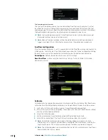
Page 5: ...nce Navico product references This manual refers to the following Navico products Broadband Radar Broadband Radar Broadband Sounder Broadband Sounder DownScan Overlay Overlay GoFree GoFree StructureScan StructureScan About this manual This manual is a reference guide for installing units Some features may not be activated or available for screenshots in the manual As a result screenshots of menus ...

Page 6: ...tor details 17 J1939 connector details 18 Ethernet connector details 18 Video in connector details 19 HDMI connector details 20 Software setup 20 First time startup 20 Software setup sequence 20 Accessing the settings dialog 20 System settings 22 Alarms settings 22 Radar settings 24 Echosounder settings 27 Autopilot settings 27 Fuel settings 29 Wireless settings 31 Network settings 36 3rd party su...

Page 7: ...H InstallationManual ban dg c om F G E A Display unit B Suncover C Bezels 1 set black bezels 1 set silver bezels D Power cable fuse fuse holder and connector block E RJ45 to 5 pin Ethernet adapter cable F NMEA 0183 connector block G Documentation pack H Cable retainer kit I NMEA 2000 starter kit J Panel mounting kit 1 Introduction Zeus3 Glass Helm Installation Manual 7 ...

Page 8: ...on split screen Default with an autopilot connected to the system Short press opens the autopilot controller and puts the autopilot in standby mode Long press toggles between panels on split screen Connectors A B C C D D D E F G G H J I A NMEA 2000 NMEA 2000 data B J1939 J1939 engine data C USB mouse keyboard or mass storage D NETWORK 1 3 Ethernet network E SD microSD card reader F HDMI OUT HDMI v...

Page 9: ...Do not download transfer or copy files to a chart card Doing so can damage chart information on the chart card If the card reader has a protective door it should always be securely shut immediately after inserting or removing a card in order to prevent possible water ingress Introduction Zeus3 Glass Helm Installation Manual 9 ...

Page 10: ...egative way A well placed external wireless module can be added to overcome poor performance Consider the optimum viewing angles Consider the overall width and height requirements Consider access to the card reader Leave sufficient clearance to connect all relevant cables Check that it is possible to route cables to the intended mounting location Ú Note Where flush mounted the enclosure should be ...

Page 11: ... way that it applies strain to the cable or causes the plug or socket to be bent out of alignment Panel mounting Refer to the separate mounting template for panel mounting instructions Bracket mounting For bracket mounting refer to separate documentation supplied with the bracket kit sold separately Installation Zeus3 Glass Helm Installation Manual 11 ...

Page 12: ...eave room adjacent to connectors to ease plugging and unplugging of cables Warning Before starting the installation be sure to turn electrical power off If power is left on or turned on during the installation fire electrical shock or other serious injury may occur Be sure that the voltage of the power supply is compatible with the unit Warning The positive supply wire red should always be connect...

Page 13: ...er Power control connection The yellow wire in the power cable can be used to control how the unit is turned on and off Power controlled by power key The unit will turn on off when the power key on the unit is pressed Leave the yellow power control wire disconnected and tape or heat shrink the end to prevent shorting Power control by supply power The unit will turn on off without using the power k...

Page 14: ... an output that turns on other devices when the unit is powered on It can be configured at the installation stage to control the power state of displays and compatible devices When commissioning the system the unit can be set to be a power control slave or power control master A A B Key Purpose Color A Power control wire Yellow B Master slave bus If a unit is configured as power control master and...

Page 15: ...ive USB cable NMEA 0183 connector details 4 3 2 1 8 7 6 5 10 9 4 3 2 1 8 7 6 5 10 9 Unitsocket male n n n n n Cableplug female Pin Top row Bottom row Purpose 1 Port 1 Port 3 TX_B 2 Port 1 Port 3 TX_A 3 Port 1 Port 3 RX_B 4 Port 1 Port 3 RX_A 5 Port 2 Port 4 TX_B 6 Port 2 Port 4 TX_A 7 Port 2 Port 4 RX_B 8 Port 2 Port 4 RX_A 9 Port 2 Port 4 Common 10 Port 2 Port 4 Shield n 4 to 10 pin connector s c...

Page 16: ...A 2000 devices The backbone needs to run within 6m 20ft of the locations of all products to be connected typically in a bow to stern layout The following guidelines apply The total length of the backbone should not exceed 100 meters 328 ft A single drop cable has a maximum length of 6 meters 20 ft The total length of all drop cables combined should not exceed 78 meters 256 ft The backbone needs to...

Page 17: ...al point in the backbone to balance the voltage drop of the network Make the installation such that the load current draw on each side of the power node is equal Ú Note 1 LEN Load Equivalency Number equals 50 mA current draw 4 LEN 8 LEN 8 LEN T T 2 LEN 2 LEN 3 LEN 1 LEN 3 LEN 1 LEN Ú Note Do not connect the NMEA 2000 power cable to the same terminals as the engine start batteries autopilot compute...

Page 18: ...e FLIR cameras are plug and play when used in conjunction with a device acting as a DHCP host For setup on networks not utilizing a DHCP host refer to the website www bandg com or contact technical support Video in connector details 1 2 Unitsocket female 1 2 Cableplug male Pin Purpose 1 Ground 2 Signal Video in The unit can be connected to two composite video sources and display video images on it...

Page 19: ...amplifier or use HDMI CAT6 adaptors HDMI out If the unit has a HDMI output it can be connected to an external monitor to replicate video at a remote location The image is shown on the external monitor at the units own native resolution so the external monitor should support the same resolution or be able to scale Ú Note Some HDMI TV displays may apply over scan which will in effect crop the image ...

Page 20: ...tion refer to Networksettings on page 31 Make sure that the proper external data sources have been selected 4 Feature setup Configure specific features as described later in this chapter Accessing the settings dialog The following sections focus on settings that typically do not require change once configured The software setup is done from the Settings dialog which can be accessed from the home p...

Page 21: ...able or disable features that are not automatically enabled or disabled by the system Rotating mast compensation If the vessel is fitted with a rotating mast it will impact any sensors or radar mounted to it Provided the mast is also fitted with a sensor to measure rotation the effect can be compensated for Ú Note If using H5000 with a rotating mast use mast rotation for wind needs to be disabled ...

Page 22: ...enabled option must be set in order for the unit to activate the buzzer when an alarm condition arises Its setting also determines the operation of the external alarm output Radar settings Ú Note The installation can vary depending on the radar Follow the installation and setup instructions supplied with the radar Use the Radar Installation dialog to setup the radar Radar source In a system with m...

Page 23: ...e this problem Ú Note This procedure must be performed with only one radar on the network and only applies where a network combines an older MFD with other MFDs Adjust range offset Pulse Radar only The radar sweep should commence at your vessel a radar range of zero You may need to adjust the radar range offset to achieve this If this is set incorrectly a large dark circle in the center of the swe...

Page 24: ...s is degraded The increased sidelobe returns can be eliminated using the Sidelobe Suppression control By default this control is set to Auto and normally should not need to be adjusted However if there is significant metallic clutter around the radar sidelobe suppression may need to be increased The control should be adjusted as follows 1 Set Radar range to between 1 2 nm to 1 nm and Sidelobe Supp...

Page 25: ...r depth readings do not account for the distance from the transducer to the lowest point of the boat in the water or from the transducer to the water surface B A B A To show the depth from the lowest point of the vessel to the bottom set the offset equal to the vertical distance between the transducer and the lowest part of the vessel A negative value To show the depth from the water surface to th...

Page 26: ... the depth from the water surface to the bottom set the offset equal to the vertical distance between the transducer and the water surface B positive value For depth below transducer set the offset to 0 Water speed calibration Water speed calibration is used to adjust the speed value from the paddle wheel to match the actual boat speed through the water Actual speed can be determined from GPS spee...

Page 27: ...or setup information refer to the Operator Manual Autopilot settings For setup and commissioning of autopilot computers refer to the documentation included with your autopilot system or autopilot computer Ú Note The WheelKey can be used as a standby key when configured for autopilot control To configure the WheelKey refer to ConfigureWheelKey on page 20 Fuel settings The fuel utility monitors a ve...

Page 28: ...faults the device which clears all user settings Reset Fuel Flow restores only the Fuel K Value setting if set in Calibrate Only Navico devices can be reset Calibrate Calibration may be required to accurately match measured flow with actual fuel flow Access calibration from the Refuel dialog Calibration is only possible on Navico s Fuel Flow sensor 1 Start with a full tank and run the engine as it...

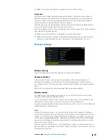
Page 29: ...ly connect without needing a password each time This menu also allows disconnection of devices that no longer require access Refer to the User Manual for information about how to connect controllers Wireless devices This dialog shows the available wireless devices as well as their IP and channel number Selecting a device provides additional detail To view and change internal wireless detail values...

Page 30: ...nel Only visible if the internal wireless is set to Access Point Internal Wifi mode when the device is selected Select it to change the Channel setting to overcome potential interference to the internal wireless by another RF device transmitting in the same frequency band Restore defaults Deletes all user made changes and restores the wireless to factory settings Client settings Opens the Wireless...

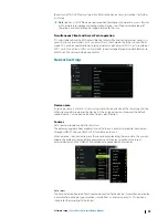
Page 31: ...rk settings Device name Assigning a name is useful in systems using more than one device of the same type and size When viewing data sources or the device list the assigned name will append the default product name virtual device function for easy identification Sources Data sources provide live data to the system The data may originate from modules internal to the unit or external modules connect...

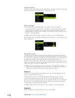
Page 32: ...ced Source Selection An example of this is where twin installations with NMEA 2000 compliant engines are not programmed with unique instance numbers This means that the auto select feature cannot determine which engine is fitted on the port and which is fitted on the starboard side Ú Note The Advanced option is visible in multiple places the bottom of the Sources list and under each source categor...

Page 33: ...or its buffer before the driver could read them Rx Tx Errors These two numbers increase when there are error messages and decrease when messages are received successfully These unlike the other values are not a cumulative count Under normal operation these should be at 0 Values around 96 upwards indicate a heavily error prone network If these numbers go too high for a given device it will automati...

Page 34: ...ypoint Select this option to allow this unit to send waypoints to another device via NMEA 2000 Ú Note The system can only transmit or receive one waypoint at a time on creation of that waypoint For bulk import or export of waypoints see the operator manual NMEA 0183 setup The NMEA 0183 port s must be set to suit the speed of connected devices and can be configured to output only the sentences requ...

Page 35: ...and made available to tablet devices and PCs via the internal wireless or Ethernet The dialogue provides IP and port data typically required for configuring the application on the third party device Ú Note Other MFDs cannot decode this information back to NMEA 0183 to use the data as a source To share data a physical NMEA 2000 or NMEA 0183 connection is still required Software setup Zeus3 Glass He...

Page 36: ...CZone Config File which is stored on all CZone modules and the Zeus Glass Helm The file is created using the CZone Configuration Tool a specialized PC application available from BEP Marine Ltd and associated CZone distributors For more information refer to the documentation provided with your CZone system Assigning the dipswitch setting Every product capable of controlling and viewing CZone device...

Page 37: ...Appendix Accessories The most up to date accessories list is available at www bandg com 6 Appendix Zeus3 Glass Helm Installation Manual 37 ...

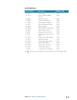
Page 38: ...7493 Transmission Parameters Dynamic 127503 AC input status 127504 AC Output Status 127505 Fluid Level 127506 DC Detailed Status 127507 Charger Status 127508 Battery Status 127509 Inverter Status 128259 Speed Water referenced 128267 Water Depth 128275 Distance Log 129025 Position Rapid Update 129026 COG SOG Rapid Update 129029 GNSS Position Data 129033 Time Date 129038 AIS Class A Position Report ...

Page 39: ...idity 130314 Actual Pressure 130576 Small Craft Status 130577 Direction Data NMEA 2000 PGN transmit 126208 ISO Command Group Function 126992 System Time 126996 Product Info 127237 Heading Track Control 127250 Vessel Heading 127258 Magnetic Variation 128259 Speed Water referenced 128267 Water Depth 128275 Distance Log 129025 Position Rapid Update 129026 COG SOG Rapid Update 129029 GNSS Position Dat...

Page 40: ... RMC RMB XTE XDR TX RX Sonar Receive DBT DPT MTW VLW VHW Transmit DBT DPT MTW VLW VHW TX RX Compass Receive HDG HDT HDM Transmit HDG TX RX Wind Receive MWV MWD Transmit MWV MWD TX RX AIS DSC Receive DSC DSE VDM Ú Note AIS sentences are not bridged to or from NMEA 2000 TX RX MARPA Transmit TLL TTM Ú Note These are only output sentences 40 Appendix Zeus3 Glass Helm Installation Manual ...

Page 41: ... 127489 109 65263 Engine Coolant Pressure 127489 94 65263 Engine Fuel Delivery Pressure 127489 92 61443 Engine Percent Load at Current Speed 127489 513 61444 Actual Engine Percent Torque 127489 189 65214 Engine Rated Speed 127498 237 65260 Vehicle Identification Number 127498 234 65242 Software Identification 127498 523 61445 Transmission Current Gear 127493 127 65272 Transmission Oil Pressure 127...

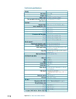
Page 42: ...60 C 4 F to 140 F Waterproof rating IPX6 when panel mounted correctly with only the front exposed Humidity IEC 60945 Damp heat 66 C 150 F at 95 relative 48 hr Shock and vibration 100 000 cycles of 20 G Interface Connectivity Ethernet 3x RJ45 USB 3x USB A J1393 1x Micro C NMEA 2000 1x Micro C NMEA 0183 4 ports Video output 1x high definition video output 1080p no HDCP HDMI A Video input 2x composit...

Page 43: ...Mounting type Panel mount or bracket optional accessory Appendix Zeus3 Glass Helm Installation Manual 43 ...

Page 44: ...15 75 475 mm 18 70 260 mm 10 24 225 mm 8 84 8 mm 0 32 19 510 mm 20 08 214 mm 8 42 478 5 mm 18 82 305 mm 12 01 8 mm 0 32 24 386 mm 15 20 8 mm 0 32 625 5 mm 24 61 649 mm 25 55 214 mm 8 42 44 Appendix Zeus3 Glass Helm Installation Manual ...

Page 45: ......

Page 46: ... 988 11997 001 ...

Reviews: