

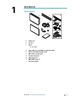

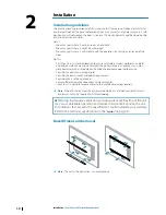


Wiring
Wiring guidelines
Don't:
•
Make sharp bends in the cables
•
Run cables in a way that allows water to flow down into the connectors
•
Run the data cables adjacent to radar, transmitter, or large/high current carrying cables or
high frequency signal cables.
•
Run cables so they interfere with mechanical systems
•
Run cables over sharp edges or burrs
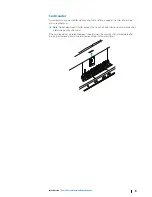
Do this:
•
Make drip and service loops
•
Use cable-tie on all cables to keep them secure
•
Solder/crimp and insulate all wiring connections if extending or shortening the cables.
Extending cables should be done with suitable crimp connectors or solder and heat
shrink. Keep joins as high as possible to minimize possibility of water immersion.
•
Leave room adjacent to connectors to ease plugging and unplugging of cables
Warning:
Before starting the installation, be sure to turn electrical power
off. If power is left on or turned on during the installation, fire, electrical
shock, or other serious injury may occur. Be sure that the voltage of the
power supply is compatible with the unit.
Warning:
The positive supply wire (red) should always be connected to
(+) DC with the supplied fuse or a circuit breaker (closest available to fuse
rating).
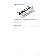
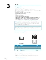
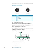
Power connector details
4
3
2
1
Unit socket
(male)
4
3
2
1
Cable plug (female)
Pin
Purpose
Color
1
DC negative
Black
2
+12/24 V DC
Red
3
External alarm
Blue
4
Power control
Yellow
Power connection
The unit is designed to be powered by a 12 or 24 V DC system.
It is protected against reverse polarity, under voltage, and over voltage (for a limited
duration).
3
12
Wiring
| Zeus3 Glass Helm Installation Manual
Summary of Contents for Zeus3 Glass Helm
Page 1: ...ENGLISH Zeus3 GlassHelm Installation Manual www bandg com ...
Page 2: ......
Page 45: ......
Page 46: ... 988 11997 001 ...


