


|
9
System introduction |
H5000 Installation
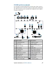
H5000 system example
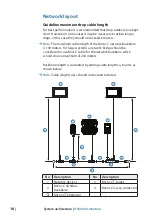
An example of a typical H5000 system. At the centre of the system is
the Central Processor Unit (CPU). All sensor information is fed back to
the CPU and can be easily controlled and confi gured via the Graphic
Display or webserver.
12V
12V
12V
12V
2
3
4
5
6
7
8
9
12
10
11
1
18
17
T
T
13
19
16
15
14
12V
PILOT
20
WIFI-1
No. Description
No. Description
1
213 Masthead unit
11
3D Motion sensor
2
HV Display
12
Alarm module
3
Graphic Display
13
Wireless Access Point or
Router
4
Race display
14
H5000 CPU
5
Analog display
15
Man Overboard Button
6
Zeus Touch
16
H5000 Pilot Computer
7
H5000 Pilot Controller
17
Rudder Feedback Unit
8
Heading sensor
18
Hydraulic Ram
9
GPS antenna
19
Speed sensor
10
High-Resolution Barometer
20
Depth sensor
T
Micro-C Terminator
12V
12 Volt DC power


