Documentation Number 3PCIOSD2x-3903 Manual
Chapter 2
7
B&B Electronics Mfg Co – 707 Dayton Rd - PO Box 1040 - Ottawa IL 61350 - Ph 815-433-5100 - Fax 815-433-5104
B&B Electronics Ltd – Westlink Comm. Pk. – Oranmore, Galway, Ireland – Ph +353 91-792444 – Fax +353 91-792445
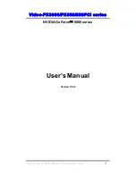
PORT 1 JP3
A 232
B 232
C 232
D 232
422/ 485
422/ 485
422/ 485
422/ 485
PORT 1
TX 422
RX 422
I N
485
485
OUT
PORT 2
A 232
B 232
C 232
D 232
422/ 485
422/ 485
422/ 485
422/ 485
CONTROL
RTS ( 232)
RTS ( 232)
SD PORT 1
SD PORT 2
CLOCK
*4
*1
TERM
I NATI ON
PORT 2
TX 422
RX 422
I N
485
485
OUT
TERM
I NATI ON
JP4
JP6
JP5
JP2
JP1
CONNECTED
NO M
EANI NG
RS-232 Mode
To configure one port for RS-232 mode, 5 jumpers must be
set/checked (5 for each port). The following settings will configure
Port 1 as RS-232.
Jumpers for Port 2 shown in italics
.
1. Set the four jumpers of JP3 (A-D) to the "232" (left) position.
Use JP5 for Port 2.
2.
Set the top Control jumper (Port 1) of JP2 to "RTS (232)" (left)
position.
Use the lower Control jumper (Port 2) for Port 2.
The remaining jumpers, JP4 and JP6, are unused in the RS-232
mode and may be in either position. Figure 2 shows the jumper
configuration to set both ports for RS-232 mode with *1 clock
enabled.
Figure 2. RS-232 Mode Jumper Settings
RS-232 Pinouts
The RS-232 ports on the 3PCIOSD2x cards are configured as
standard DTE RS-232 serial ports.
Table 1
shows the signal
connections on the DB-9 male connectors.