IT5000-C / IT6000-C
3/8” IT Tool
www.BAND-IT-IDEX.com
Document # P48850 Rev. C
© Copyright
BAND-IT-IDEX, Inc. 2015
All rights reserved
Page 14 of 36
BAND-IT-IDEX, Inc.
A Unit of IDEX Corporation
4799 Dahlia Street
Denver, CO 80216-3070 USA
P: 1-800-525-0758
F: 1-800-624-3925
Operating
Manual
1.
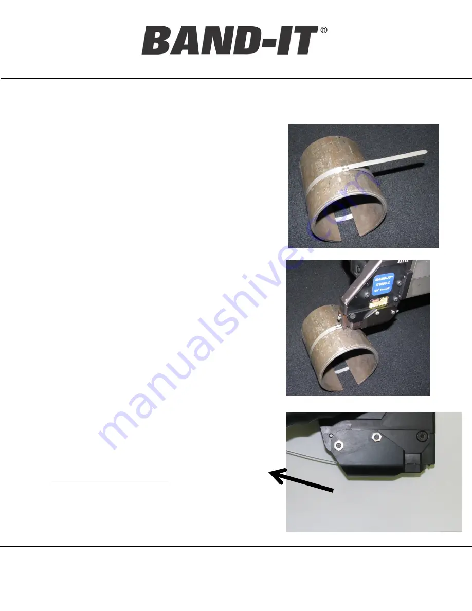
(Tie-Lok Tie only) Lace the tie snug around
the assembly and locate the buckle in the
target location.
2.
Band should be applied to a uniform solid
surface allowing the buckle adequate support
during the clamp locking and clamp tail cut-off
operation. (pg. 17)
3.
Insert the tail of the clamp all the way through
the tool bringing the tool head as close to the
buckle as possible. The tail length extending
into tool must be at least 2.5” (6.4 cm) long.
4.
Do not activate tool while inserting clamp tail
because this can cause tie tail to jam in the
Tension Block Assembly.
5.
Ensure proper tool orientation. (pg. 15)
6.
Begin tensioning by pushing and holding down
operating trigger or by using the remote
trigger system. If the trigger is released, the
tool will cease operation if the desired tension
has not been achieved.
7.
While tensioning clamp, allow the tool to move
freely.(pg.15) Continue to hold down operating
trigger until tool completely tensions and cuts
off clamp. Release trigger after cut off.
8.
After clamp is completed, clamp tail scrap
must be removed from tool. Clamp tail scrap
is not ejected automatically. Tool is now ready
for next tie/clamp.
Tie-Lok
®
Tie / Jr
®
Clamp Installation Procedure
Note: Trigger activation requires approximately 3 lbs.f


