background image

11 / 22

0006081529_201201

COMBUSTION ADJUSTMENT 

00

02

93

41

90

PYCCKИИ

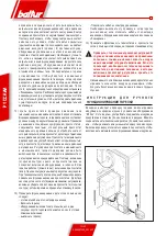
РЕГУЛИРОВКА ВОЗДУХА НА ГОЛОВКЕ 

ГОРЕНИЯ


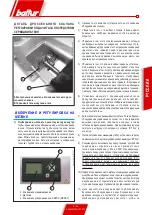
Головка горения оснащена устройством регулировки, которое 

позволяет открывать или закрывать проход воздуха между 

диском и головкой. Таким образом, закрывая проход, получается 

высокое давление раньше диска и в случае невысоких подачей. 

Высокая скорость и турбулентность воздуха способствуют 

ее лучшему проникновению в горючее и, поэтому, отличной 

смеси и стабильности пламени. Может быть необходимо иметь 

высокое давление воздуха раньше диска, чтобы избежать 

пульсаций пламени. Данное условие необходимо, когда горелка 

работает на герметизированной топке и/или с высокой тепловой 

нагрузкой.  Из  вышесказанного,  остается  понятным,  что 

устройство, закрывающее воздух на головке горения, должен 

быть установлено на определенное положение, чтобы получать 

всегда

 очень высокий уровень давления воздуха за диском . 

Рекомендуется выполнить регулировку так, чтобы осуществить 

закрытие  воздуха  на  головке.  Данное  закрытие  требует 

значительного открытия задвижки воздуха, регулирующей поток 

воздуха вентилятора горелки. Это происходит когда горелка 

работает на максимальной желаемой подаче. Необходимо 

начать регулировку посредством устройства, закрывающего 

воздух  на  головке  горения  в  промежуточном  положении, 

включая горелку для ориентировочной регулировки, как уже 

было сказано.

При  достижении 

максимальной  желаемой  подачи


исправляется положение устройства, закрывающего воздух 

на  головке  горения  и  передвигается  вперед  или  назад 

(0002934190),  чтобы  получить  подходящий  поток  воздуха 

с задвижкой регулировки воздуха при чувствительно 

открытой высасывании. 

!

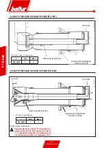
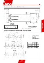
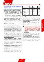
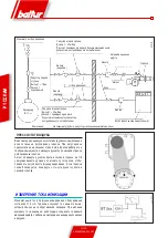
  Чтобы облегчить операцию регулировки головки 

горения, рекомендуется смотреть таблицы ( рис. 

0002935000 для BTG 15ME, рис. 0002934171 для BTG 

20ME и рис. 0002935180 для BTG 28ME).

При  уменьшении  перехода  воздуха  на  головке  горения, 

необходимо предотвратить полное закрытие, которое могло бы 

вызывать чрезмерное нагревание головки и последовательную 

быструю порчу.  

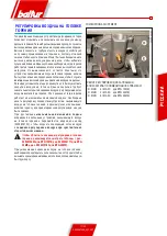
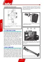
D ВИНТ РЕГУЛИРОВКИ ДИСКА ПЛАМЕНИ

Е ПОКАЗАТЕЛЬ ПОЛОЖЕНИЯ ДИСКА ПЛАМЕНИ:

(0 = МИН     4 = МАКС    для BTG 15ME)

(0 = МИН     3 = МАКС    для BTG 20ME)

(0 = МИН     4 = МАКС    для BTG 28ME)

Summary of Contents for btg 15 me

Page 1: ...MODULATING GAS BURNERS WITH BT 320 ELECTRONIC CAM UK Manuel d instructions pour l utilisation BRULEUR DE GAZ A DEUX ALLURES PROGRESSIVES MODU LANTES AVEC CAME ELECTRONIQUE BT 320 FR Manual de instruc...

Page 2: ......

Page 3: ...p www baltur com E MAIL info baltur it 18 11 2010 Declaration of Conformity We declare that our products BPM BGN BT BTG BTL TBML Comist GI GI Mist Minicomist PYR RiNOx Spark Sparkgas TBG TBL TBML TS I...

Page 4: ...er or if the owner moves and leaves the equipment make sure that the booklet always goes with the equipment so it can be consulted by the new owner and or installer For all equipment with optionals or...

Page 5: ...t law and regulations since incorrect installation may cause damage to person animals or things for which damage the manufacturer shall not can be held responsible Before installation it is advisable...

Page 6: ...otal absorption at start with ignition transformer on TECHNICAL SPECIFICATIONS TECHNICAL AND FUNCTIONAL SPECIFICATIONS Two stage progressive output operation Ability to operate with output modulation...

Page 7: ...ressure switch to ensure the presence of combustive air Combustive air flow rate adjustment by means of the step servo motor Gas train consisting of a butterfly valve controlled by a step servo motor...

Page 8: ...S MOD A A1 A2 B B1 B5 C D min D max E F N M L min L max I1 I BTG 15ME 303 158 145 345 275 70 680 150 280 126 114 135 M10 170 210 185 185 BTG 20ME 303 158 145 345 275 70 695 150 300 127 114 135 M10 170...

Page 9: ...joint must be installed upstream of the gas valve as shown in the diagram 1 Manual shut off valve 2 Anti vibration joint 3 Gas filter 4 Minimum gas pressure switch 5 Safety solenoid valve 6 Pressure r...

Page 10: ...vice ionization probe immersed in the flame The programmer relay moves past the locking position and sends voltage to the air gas supply regulation servo motors which go to the minimum point 200 If th...

Page 11: ...ption For burner adjustment refer to the supplied instructions for the BT 3xx electronic cam 8 After having adjusted the minimum 200 bring the burner towards the maximum using the controls on the BT 3...

Page 12: ...itch that stops the burner actually operates i e opens the circuit 13 Verify the flame detector operation as follows disconnect the wire coming from the ionization electrode Start up the burner The eq...

Page 13: ...head that will require a significant opening of the air shutter that regulates the flow from the burner fan output This must of course be the case when the burner is working at the maximum required s...

Page 14: ...X Min Max BTG 15ME 59 75 IGNITION ELECTRODES BOILER COUPLING FLANGE GAS INLET BTG 15ME COMBUSTION HEAD ADJUSTMENT DIAGRAM IGNITION ELECTRODES BOILER COUPLING FLANGE GAS INLET X Min Max BTG 20ME 5 13 X...

Page 15: ...head distance IGNITION ELECTRODES BOILER COUPLING FLANGE GAS INLET 1 Ionizing electrode 2 Ignition electrode 3 Flame disk 4 Mixer 5 Gas outlet pipe A B C BTG 15ME 79 2 BTG 20ME 5 2 3 8 5 BTG 28ME 5 2...

Page 16: ...ose the fuel valve and to disconnect the burner electrically MAINTENANCE The burner does not require any particular maintenance However it is advisable to analyse combustion gases and check that the e...

Page 17: ...ing at least 1 15 the surface area of the room with a minimum of 0 5 m2 At least one third of the entire area of these inlets must be located in the lower part of the external wall flush with the floo...

Page 18: ...e air pressure switch adjusted to the start of the scale With the burner operating at the requested power level slowly turn the adjustment knob clockwise until the burner locks out Then turn the knob...

Page 19: ...operation of the air pressure switch The burner starts and the flame ignites but then the burner locks out 1 The control electrode does not detect or detects the flame improperly 1 Check the position...

Page 20: ...18 22 0006081529_201201 ENGLISH ENGLISH...

Page 21: ...19 22 0006081529_201201 ENGLISH...

Page 22: ...20 22 0006081529_201201 ENGLISH ENGLISH...

Page 23: ...XTERNAL BLOCK LAMP H1 OPERATION LIGHT MV MOTOR N1 REGULATEUR ELECTRONIQUE P M GAS MAX PRESSURE SWITCH P1 HOUR METER PA AIR PRESSURE SWITCH Pm GAS MIN PRESSURE SWITCH S2 RE SET PUSH BUTTON SG GENERAL S...

Page 24: ...22 22 0006081529_201201 ENGLISH ENGLISH...

Page 25: ...INFORMACI N I PELIGRO ATENCI N Antes de empezar a utilizar el quemador leer detenidamente el folleto ADVERTENCIAS DIRIGIDAS AL USUARIO PARA USAR EL QUEMADOR CON SEGURIDAD que va con el manual de inst...

Page 26: ...libro de instruccionesest siempreconelaparatoparaquepuedaserconsultado por el nuevo propietario y o instalador Para todos los aparatos con elementos opcionales o kits incluidos los el ctricos hay que...

Page 27: ...namiento el aparato el personal cualificado profesionalmente tiene que controlar a la estanqueidad en el tramo interior y exterior de los tubos de abastecimiento del combustible b la regulaci n del ca...

Page 28: ...etapa de arranque con transformador de encendido accionado CARACTER STICAS T CNICAS CARACTER STICAS T CNICO FUNCIONALES Funcionamiento en dos etapas progresivas de potencia Posibilidad de funcionamie...

Page 29: ...omburente a trav s de servomotor el ctrico paso a paso Rampa de gas con v lvula de mariposa mandada por servomotor el ctrico paso a paso por v lvula de monobloque que incluye v lvula de funcionamiento...

Page 30: ...ONES GENERALES MOD A A1 A2 B B1 B5 C D m n D m x E F N M L m n L m x I1 I BTG 15ME 303 158 145 345 275 70 680 150 280 126 114 135 M10 170 210 185 185 BTG 20ME 303 158 145 345 275 70 695 150 300 127 11...

Page 31: ...sostato de presi n m nima del gas 5 V lvula de seguridad 6 Regulador de presi n 7 Dispositivo de control de estanqueidad de las v lvulas 8 V lvula de trabajo 9 Servomotor de regulaci n del aire 10 Cla...

Page 32: ...servomotores de regulaci n de suministro aire gas que se desplazan hacia el punto m nimo 200 Si el termostato de la caldera o pres stato de segunda etapa lo permite programado en un valor de temperat...

Page 33: ...iene que estar abierto Ver el cap tulo Regulaci n del aire en el cabezal de combusti n 6 Aplicar un man metro con escala adecuada si la entidad de la presi n prevista lo permite es preferible utilizar...

Page 34: ...consecuentemente del quemador Cuando el quemador funciona llama encendida la activaci n de los pres statos del gas apertura del circuito ocasiona inmediatamente el bloqueo del quemador En el acto de l...

Page 35: ...ire en el cabezal que requiera una consistente apertura de la clapeta del aire de regulaci n del flujo de salida del ventilador quemador Por supuesto esta condici n tiene que realizarse cuando el quem...

Page 36: ...IDA DE UNI N A LA CALDERA ENTRADA DEL GAS ESQUEMA DE REGULACI N DEL CABEZAL DE COMBUSTI N BTG 15ME ELECTRODOS DE ENCENDIDO BRIDA DE UNI N A LA CALDERA ENTRADA DEL GAS X M n M x BTG 20ME 5 13 X Distanc...

Page 37: ...NI N A LA CALDERA ENTRADA DEL GAS 1 Electrodo ionizador 2 Electrodo de encendido 3 Disco llama 4 Mezclador 5 Tubo de env o del gas A B C BTG 15ME 79 2 BTG 20ME 5 2 3 8 5 BTG 28ME 5 2 3 5 ESQUEMA DE CO...

Page 38: ...entaci n el ctrica MANTENIMIENTO El quemador no necesita un mantenimiento especial ser oportuno efectuar por lo menos una vez al a o y seg n las normas vigentes la an lisis de los gases de escape veri...

Page 39: ...l local de un m nimo de 0 5 m2 Por lo menos un tercio de la superficie total de dichas aperturas tiene que estar colocado en la parte inferior de la pared externa a ras del suelo 3 Activaciones de la...

Page 40: ...l pres stato regulado al principio de la escala Mientras el quemador funciona a la potencia requerida girar la manija de regulaci n en sentido horario hasta el bloqueo del quemador A continuaci n gira...

Page 41: ...e enciende se crea la llama luego se bloquea 1 Falta de detecci n o detecci n insuficiente de la llama por parte del electrodo de control 1 Controlar la colocaci n del electrodo de control Controlar e...

Page 42: ...18 22 0006081529_201201 ESPA OL ESPA OL...

Page 43: ...19 22 0006081529_201201 ESPA OL ESPA OL...

Page 44: ...20 22 0006081529_201201 ESPA OL ESPA OL...

Page 45: ...INDICADORA FUNZIONAMIENTO RESISTENCIAS AUXILIAR H1 LUZ INDICADORA DE FUNZIONAMIENTO MV MOTOR IMPULSOR N1 REGULADOR ELECTRONICO P M PRESOSTATO DE MAX P1 CONTADOR DE HORAS PA PRESOSTATO AIRE Pm PRESOSTA...

Page 46: ...22 22 0006081529_201201 ESPA OL ESPA OL...

Page 47: ...info baltur it 18 11 2010 D claration de Conformit Nous d clarons que nos produits BPM BGN BT BTG BTL TBML Comist GI GI Mist Minicomist PYR RiNOx Spark Sparkgas TBG TBL TBML TS IBR IB Variante LX pou...

Page 48: ...ser ce dernier toujours v rifier que la notice accom pagne l appareil afin qu il puisse tre consulter par le nouveau propri taire et ou par l installateur Pour tous les appareils avec options ou kit y...

Page 49: ...tuer les v ri fications suivantes par du personnel qualifi a le contr le de l tanch it de la partie interne et externe des tuyaux d arriv e du combustible b la r glage du d bit du combustible en fonct...

Page 50: ...e au d marrage avec transformateur d allumage activ CARACTERISTIQUES TECHNIQUES C A R A C T E R I S T I Q U E S T E C H N I Q U E S FONCTIONNELLES Fonctionnement deux allures progressives de puissance...

Page 51: ...rant R glage du d bit d air comburant par servomoteur lectrique pas pas Rampe gaz constitu e par une vanne papillon command e par un servomoteur lectrique pas pas par une vanne monobloc comprenant une...

Page 52: ...ENT MOD A A1 A2 B B1 B5 C D min D max E F N M L min L max I1 I BTG 15ME 303 158 145 345 275 70 680 150 280 126 114 135 M10 170 210 185 185 BTG 20ME 303 158 145 345 275 70 695 150 300 127 114 135 M10 1...

Page 53: ...barrage manuel et un joint amortisseur dispos s d apr s le sch ma 1 Vanne de barrage manuel 2 Joint amortisseur 3 Filtre gaz 4 Pressostat de pression minimale du gaz 5 Vanne de s curit 6 R gulateur d...

Page 54: ...e la position de blocage et transmet la tension aux servomoteurs de r glage du d bit air gaz qui se portent au point minimum 200 Si le thermostat de chaudi re ou le pressostat de 2 me allure le permet...

Page 55: ...ne d eau ne pas utiliser d instrument aiguille pour des pressions faibles la prise de pression pr vue sur le pressostat gaz 7 Activer maintenant l interrupteur g n ral L appareil de commandere oitains...

Page 56: ...rmine imm diatement l arr t du br leur Le r glage des pressostats de pression de gaz minimale et maximale doit avoir lieu la premi re mise en marche du br leur en fonction de la pression relev e au fu...

Page 57: ...r sur la t te demandant une ouverture sensible du volet d air qui r gle le flux vers la sortie du ventilateur du br leur bien entendu cette condition doit se v rifier quand le br leur fonctionne la di...

Page 58: ...75 ELECTRODES D ALLUMAGE BRIDE DE FIXATION DE LA CHAUDIERE ARRIVEE GAZ SCHEMA DE REGLAGE DE LA TETE DE COMBUSTION BTG 15ME ELECTRODES D ALLUMAGE BRIDE DE FIXATION DE LA CHAUDIERE ARRIVEE GAZ X Min Ma...

Page 59: ...RODES D ALLUMAGE BRIDE DE FIXATION DE LA CHAUDIERE ARRIVEE GAZ 1 lectrode ionisateur 2 lectrode allumage 3 Disque flamme 4 M langeur 5 Tuyau de refoulement du gaz A B C BTG 15ME 79 2 BTG 20ME 5 2 3 8...

Page 60: ...rique ENTRETIEN Le br leur ne n cessite pas d entretien particulier Dans tous les cas il convient d analyser au moins une fois par an les gaz d chappement de la combustion en v rifiant l exactitude de...

Page 61: ...m2 Au moins un tiers de la surface totale de ces ouvertures doit tre situ dans la partie inf rieure des murs ext rieurs au ras du sol 3 Ex cution de l installation de gaz liquide afin de garantir un f...

Page 62: ...u d but de l chelle Lorsque le br leur fonctionne la puissance requise agir sur la poign e de r glage dans le sens des aiguilles d une montre jusqu ce que le br leur se bloque Tourner donc la poign e...

Page 63: ...nnement du pressostat de l air Le br leur d marre il y a la formation de la flamme et puis le br leur se bloque 1 D tection de flamme manqu e ou insuffisante de la part de l lectrode de contr le 1 Con...

Page 64: ...18 22 0006081529_201201 FRAN AIS FRAN AIS...

Page 65: ...19 22 0006081529_201201 FRAN AIS FRAN AIS...

Page 66: ...20 22 0006081529_201201 FRAN AIS FRAN AIS...

Page 67: ...AMPE BLOC EXTERIEURE H1 LAMPE MARCHE MV MOTEUR N1 ELECTRONIC REGULATOR P M PRESSOSTAT MAX P1 COMPTEUR HORAIRE PA PRESSOSTAT AIR Pm PRESSOSTAT MIN S2 BOUTON DE DEBLOCAGE SG INTERRUPTEUR GENERAL TA TRAS...

Page 68: ...22 22 0006081529_201201 FRAN AIS FRAN AIS...

Page 69: ...nler bu nedenle a a daki i aretle i aretlenmi tir 0085 Dr Riccardo Fava Genel M d r CEO Br l r kullanmaya ba lamadan nce r n n b t nleyici ve gerekli par as n olu turan br l rle birlikte verilen bu t...

Page 70: ...ma k lavuzlar n n da daima cihaz n yan nda olmas n sa lay n z B ylece yeni sahibi ve veya monte eden ki i k lavuzdan yararlanabilir Opsiyonel malzemeler veya elektrik malzemesi dahil kitler de dahil o...

Page 71: ...ger ekle tirilmelidir Yanl kurulum insana hayvana ve e yaya zarar verebilir ki bu a amada retici bu zarardan sorumlu de ildir Br l r kurulumundan nce sistemin d zg n al mas n aksatacabilecek yak t be...

Page 72: ...4 ADET M10 x 50 ALTIGEN SOMUNLAR 4 ADET M10 D ZRONDELALAR 4 ADET 10 Hareket faz nda ate leme transformat r devrede iken toplam emi TEKN K ZELL KLER TEKN K FONKS YONEL ZELL KLER ki g ilerleme fazl i l...

Page 73: ...m elektrikli servomotor arac l yla yanma havas n n kapasitesinin reg lasyonu Ad m ad m elektrikli servomotor al t rma ve g venlik valfini minimum manostat valflerin s zd rmazl k kontrol n bas n reg la...

Page 74: ...MOD A A1 A2 B B1 B5 C D min D maks E F N M L min L maks I1 I BTG 15ME 303 158 145 345 275 70 680 150 280 126 114 135 M10 170 210 185 185 BTG 20ME 303 158 145 345 275 70 695 150 300 127 114 135 M10 170...

Page 75: ...da belirtilene g re yerle tirilen man el bir kesme valfi ve anti titre imli contay gaz valfinin st ne monte etmek gerekir 1 Man el kesme valfi 2 Anti titre imli conta 3 Gaz filtresi 4 Minimum gaz bas...

Page 76: ...leve batan iyonizasyon alg lay c Programlay c r le blokaj pozisyonunu a ar ve minimum noktaya 200 getirilen ikmalin hava gaz reg lasyon servomotorlar na gerilim verir E er 2 fazl kazan termostat veya...

Page 77: ...i ara lar kullanmay n z 7 imdi genel alteri devreye sokunuz B ylece kumanda cihaz gerilimi alg lar ve programlay c leyi in tan m b l m nde anlat ld gibi br l r n devreye al nmas n belirler Br l r n re...

Page 78: ...mas n belirlemesi gereken manostat n m dahalesi devrenin a lmas kontrol edilir 13 Alev alg lay c s n n i leyi ini a a daki gibi kontrol ediniz iyonizasyon elektrotundan gelen kabloyu kart n z Br l r a...

Page 79: ...n bir kapanmas n ger ekle tirecek ekilde ayarlanmas tavsiye edilir a k a bu durum br l r arzu edilen maksimum miktarda al t zaman kontrol edilmelidir Pratik olarak g sterildi i gibi br l r y nlendiril...

Page 80: ...in Maks BTG 15ME 59 75 ATE LEME ELEKTROTLARI KAZAN BA LANTI FLAN I GAZ G R BTG 15ME YANMA BA LI ININ REG LASYON EMASI ATE LEME ELEKTROTLARI KAZAN BA LANTI FLAN I GAZ G R X Min Maks BTG 20ME 5 13 X Ba...

Page 81: ...afesi ATE LEME ELEKTROTLARI KAZAN BA LANTI FLAN I GAZ G R 1 yonla t r c elektrot 2 Ate leme elektrotu 3 Alev diski 4 Kar t r c 5 Gaz da t m borusu A B C BTG 15ME 79 2 BTG 20ME 5 2 3 8 5 BTG 28ME 5 2 3...

Page 82: ...at n z ve elektrik beslemesini kesiniz BAKIM Br l r zel bir bak m gerektirmemektedir her hal karda y lda bir ve mutlak surette y r rl kteki mevzuata uygun ekilde egzoz gaz analizinin yapt r lmas ve em...

Page 83: ...nd rma giri leri olmal d r S z edilen giri ler hakk nda toplam y zeyin en az te biri d z zeminli d duvar n alt taraf na yerle tirilmelidir 3 D zg n al mas n ve g venli i sa lamak i in s v gaz tesisat...

Page 84: ...m di er reg lasyon i lemlerini ger ekle tirdikten sonra hava manostat n n reg lasyonunu ger ekle tiriniz Br l r gereken g te al rken br l r n blokaj na kadar saat y n nde reg lasyon kolu zerinde i lem...

Page 85: ...ini kontrol ediniz Br l r al yor alev olu umu var bloke durumuna gidiyor 1 Kontrol elektrotu taraf ndan alevin alg lanmamas veya yetersiz alg lanmas 1 Kontrolelektrotununkonumland n kontrol ediniz yo...

Page 86: ...18 22 0006081529_201201 T RK E...

Page 87: ...19 22 0006081529_201201 T RK E...

Page 88: ...20 22 0006081529_201201 T RK E...

Page 89: ...IK SENS R HO HARICI ARIZA LAMBASI H1 LETME LANBASI MV MOTOR N1 ELEKTRON K G REG LAT R P M MAX GAZ PRESOSTATI P1 SAYA PA HAVA PRESOSTATI Pm M N MUM GAZ PRESOSTATI S2 RESET BUTONU SG GENEL ANAHTAR TA AT...

Page 90: ...22 22 0006081529_201201 T RK E...

Page 91: ...39 051 684 37 11 Fax 39 051 683 06 86 http www baltur it http www baltur com E MAIL info baltur it BPM BGN BT BTG BTL TBML Comist GI GI Mist Minicomist PYR RiNOx Spark Sparkgas TBG TBL TBML TS IBR IB...

Page 92: ...2 22 0006081529_201201 PYCCK BALTUR I a b c a b c d e f g...

Page 93: ...3 22 0006081529_201201 PYCCK 2 RC a b c d e a b a b c d I...

Page 94: ...6 1 20 6 28 2 3 1 9 2 3 3 1 3 6 25 8 0 10 9 50 60 80 160 205 280 30 NOx 120 II EN 676 80 III EN 676 120 II EN 676 r p m 185 2800 230 50 1 230 10 50 0 370 26 40 A 230 50 LAMTEC BT 3xx 17 BTG 15ME BTG 2...

Page 95: ...60 70 80 90 100 110 120 130 140 150 160 170 180 190 200 210 220 230 240 250 260 270 280 290 300 6 7 8 9 10 11 12 13 14 15 16 17 18 19 20 21 22 23 24 25 26 27 28 29 30 2 3 4 5 6 7 8 9 10 11 2 5 3 5 4...

Page 96: ...B5 C D D E F N M L L I1 I BTG 15ME 303 158 145 345 275 70 680 150 280 126 114 135 M10 170 210 185 185 BTG 20ME 303 158 145 345 275 70 695 150 300 127 114 135 M10 170 210 185 185 BTG 28ME 303 158 145...

Page 97: ...7 22 0006081529_201201 0002934100 N 0002911020 PYCCK O 1 B C n 2 x BTG 20 28 2 F 3 4 EN 676 1 2 3 4 5 6 7 8 9 10 11 12 13 14...

Page 98: ...8 22 0006081529_201201 display lamtec BT3xx 3 4 2 PYCCK LAMTEC BT 3xx BT3xx 1 1 3 30 2 200 999 BT 3xx 3 RESET 4 2 3 4 RESET...

Page 99: ...9 22 0006081529_201201 display lamtec BT3xx 3 4 2 TBG ME Butterfly valve PYCCK 1 2 3 4 5 6 U 7 BT 3xx 8 200 BT3xx 9 200 999 CO 10 11 2 3 4 RESET A B B...

Page 100: ...10 22 0006081529_201201 PYCCK 12 13 14 BT 3xx...

Page 101: ...11 22 0006081529_201201 COMBUSTION ADJUSTMENT 0002934190 PYCCK 0002934190 0002935000 BTG 15ME 0002934171 BTG 20ME 0002935180 BTG 28ME D 0 4 BTG 15ME 0 3 BTG 20ME 0 4 BTG 28ME...

Page 102: ...2 22 0006081529_201201 N 0002935000 X Disk head distance Elettrodo accensione Flangia attacco caldaia Entrata gas N 0002934171 PYCCK X X BTG 15ME 59 75 BTG 15ME X BTG 20ME 5 13 X X NOx X 5 13 BTG 20ME...

Page 103: ...MBUSTION HEAD ADJUSTMENT DIAGRAM N 0002935180 PYCCK X BTG 28ME 40 68 X 1 2 3 4 5 A B C BTG 15ME 79 2 BTG 20ME 5 2 3 8 5 BTG 28ME 5 2 3 5 BTG 15ME BTG 20ME BTP 28ME 0002935010 tif 0002934181 tif 000293...

Page 104: ...14 22 0006081529_201201 N 0002934540 Manutenz 2 Manutenz 1 Manutenz 3 PYCCK 3 4 1 2 3 3...

Page 105: ...0006081529_201201 PYCCK 1 a 1 3 22 000 1 m3 2 4 22 000 1 3 2 4 2 1 56 0 06 n 412 4183 6 1975 1 15 0 5 2 3 15 C 10 C 5 C 0 C 5 C 990 1 6 2 5 3 5 8 10 3000 2 5 4 5 6 5 9 12 5000 4 6 5 11 5 16 21 4 300 U...

Page 106: ...16 22 0006081529_201201 8721 2 ioniz_BT3xx PYCCK 1 30 30 1 4 1 4 A...

Page 107: ...17 22 0006081529_201201 PYCCK 1 2 1 2 1 2 3 1 2 3 1 1 AD PE SS PN 40 40 1 2 3 4 18...

Page 108: ...18 22 0006081529_201201 PYCCK...

Page 109: ...19 22 0006081529_201201 PYCCK...

Page 110: ...20 22 0006081529_201201 PYCCK...

Page 111: ...21 22 0006081529_201201 PYCCK DIN IEC PYC GNYE BU BN BK BK PYC A1 B1 BP BT 1 3 HO H1 MV N1 P M P1 PA Pm S2 SG TA TC TS X1B S X2B S 2 Y8 Y10 YP YS...

Page 112: ...22 22 0006081529_201201 PYCCK...

Page 113: ......

Page 114: ...ue est titre indicatif Le constructeur se r serve donc la possibilit de modifier les donn es techniques et tout ce qui est contenu dans le catalogue El presente cat logo tiene una finalidad meramente...

Reviews: