background image

www.balluff.com

15

deutsch

Einstellverfahren

6.1 

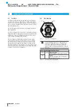
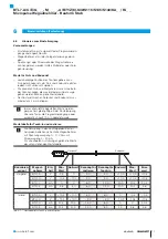
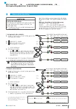
Einstellvorrichtung (nicht bei BTL7-…-S140)

Die Einstellvorrichtung ist eine Zusatzeinrichtung zum 
Einstellen des Wegaufnehmers.


Ź

Vor Beginn der Einstellung: Einstellvorrichtung auf die 
Anschlussseite des Wegaufnehmers aufsetzen.


Ź

Nach Abschluss der Einstellung: Einstellvorrichtung 
zum Schutz gegen Verstellen entfernen.


Ź

Einstellvorrichtung für eine spätere Verwendung aufbe-
wahren.

Automatische Deaktivierung!

Werden die Taster der Einstellvorrichtung 
ca. 10 min lang nicht betätigt, wird der 
Programmiermodus automatisch beendet.

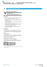
Bild 6-1: 

Taster 1 (blau)

Taster 2 (grau)

Einstellvorrichtung aufgesetzt

6.2 

Programmiereingänge  
(nicht bei BTL7-…-S135)

Statt der Einstellvorrichtung können zur Einstellung auch 
die Programmiereingänge genutzt werden.
–  La entspricht Taster 1,
–  Lb entspricht Taster 2,
–  Programmiereingang auf 20 bis 28 V (BTL7-_1_ _-...)

bzw. 10 bis 30 V (BTL7-_5_ _-...) entspricht Taster 
gedrückt (high-aktiv).

Automatische Deaktivierung!

Werden über die Programmiereingänge 
ca. 10 min keine Signale übertragen, wird der 
Programmiermodus automatisch beendet.

6.3 

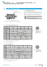
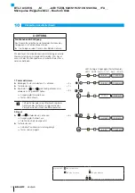
Übersicht der Einstellverfahren

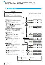
6.3.1  Teach-in

Der werkseitig eingestellte Null- und Endpunkt wird durch 
einen neuen Null- und Endpunkt ersetzt.

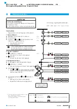
Die detaillierte Vorgehensweise für das Teach-in 
ist auf Seite 18 beschrieben.

Ablauf:


Ź

Positionsgeber in die neue Nullposition verschieben.


Ź

Neuen Nullpunkt durch Drücken der Taster einlesen.

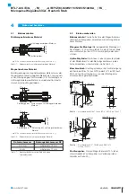
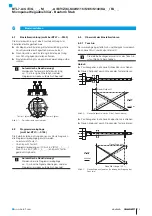
Bild 6-2: 

Neuer Nullpunkt

vorher

nachher

fallend

steigend

Neuen Nullpunkt einlesen (Offset-Verschiebung)


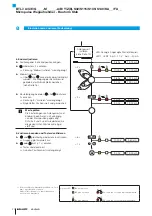
Ź

Positionsgeber in die neue Endposition verschieben.


Ź

Neuen Endpunkt durch Drücken der Taster einlesen.

Bild 6-3: 

Neuer Endpunkt

vorher

nachher

Neue Messlänge 100 %

Neuen Endpunkt einlesen (Änderung der Steigung der 
Kennlinie)

BTL7-A/C/E/G_ _ _-M_ _ _ _-A/B/Y/Z(8)-S32/S115/S135/S140/KA_ _/FA_ _
Micropulse Wegaufnehmer - Bauform Stab

Summary of Contents for BTL7 Series

Page 1: ...Betriebsanleitung deutsch BTL7 A C E G_ _ _ M_ _ _ _ A B Y Z 8 S32 S115 S135 S140 BTL7 A C E G_ _ _ M_ _ _ _ A B Y Z 8 KA_ _ FA_ _...

Page 2: ...www balluff com...

Page 3: ...ss 9 4 1 Einbauvarianten 9 4 2 Einbau vorbereiten 9 4 3 Wegaufnehmer einbauen 10 4 3 1 Einbauempfehlung f r Hydraulikzylinder 10 4 4 Elektrischer Anschluss 11 4 4 1 Steckverbinder S32 Kabelanschluss 1...

Page 4: ...ungsversorgung extern 23 11 4 Ausgang 23 11 5 Eingang 23 11 6 Ma e Gewichte 24 12 Zubeh r 25 12 1 Positionsgeber 25 12 2 Befestigungsmutter 25 12 3 Steckverbinder und Kabel 26 12 3 1 BKS S32 S33M 00 f...

Page 5: ...folgenden Fachgrundnormen EN 61000 6 1 St rfestigkeit EN 61000 6 2 St rfestigkeit EN 61000 6 3 Emission EN 61000 6 4 Emission und folgende Produktnorm EN 61326 2 3 Emissionspr fungen Funkst rstrahlung...

Page 6: ...er Betreiber hat die Verantwortung dass die rtlich geltenden Sicherheitsvorschriften eingehalten werden Insbesondere muss der Betreiber Ma nahmen treffen dass bei einem Defekt des Wegmesssystems keine...

Page 7: ...g des Wegaufneh mers sind St be mit Nennl ngen von 25 mm bis 7620 mm lieferbar 10 2 mm Nennl nge von 25 mm bis 7620 mm 8 mm Nennl nge von 25 mm bis 1016 mm D mpfungszone Messtechnisch nicht nutzbarer...

Page 8: ...der D mpfungszone absorbiert Die zum Anfang des Wellenleiters laufende Torsionswelle erzeugt in einer Abnehmerspule ein elektrisches Signal Aus der Laufzeit der Welle wird die Position bestimmt Je na...

Page 9: ...durchmesser bei Einbau in einen Hydraulikzylinder 4 2 Einbau vorbereiten Einbauvariante F r die Aufnahme des Wegaufnehmers und des Positionsgebers empfehlen wir nichtmagnetisier bares Material Waagere...

Page 10: ...liegt in der Verantwortung des Zylinderherstellers Der Werkstoff des Gleitelements muss auf den Belastungs fall das eingesetzte Medium und die auftretenden Tempe raturen abgestimmt sein M glich sind...

Page 11: ...D rot La Programmiereingang 5 GN gr n 0 10 V 10 10 V nicht belegt1 8 WH wei Lb Programmiereingang BTL7 _1_ _ BTL7 _5_ _ 6 BU blau GND2 GND2 7 BN braun 20 bis 28 V 10 bis 30 V 1 Nicht belegte Adern k n...

Page 12: ...binder S140 S140 Pin Schnittstelle BTL7 A B C J K G H E D F Bild 4 12 Pinbelegung S140 Draufsicht auf Stecker am Wegaufnehmer 10 poliger Rundstecker A_10 G_10 C_00 C_70 E_00 E_70 A 0 V B nicht belegt...

Page 13: ...Kabelschirm erden mit dem Schutzleiter verbinden Magnetfelder Das Wegmesssystem ist ein magnetostriktives System Auf ausreichenden Abstand des Wegaufnehmers und des Aufnahmezylinders zu starken exter...

Page 14: ...en oder Systemher stellers beachten 1 Anschl sse auf festen Sitz und richtige Polung pr fen Besch digte Anschl sse tauschen 2 System einschalten 3 Messwerte und einstellbare Parameter pr fen und ggf d...

Page 15: ...ster 2 Programmiereingang auf 20 bis 28 V BTL7 _1_ _ bzw 10 bis 30 V BTL7 _5_ _ entspricht Taster gedr ckt high aktiv Automatische Deaktivierung Werden ber die Programmiereing nge ca 10 min keine Sign...

Page 16: ...Bild 6 5 Neuer Endwert vorher nachher Endpunkt Neue Endposition justieren nderung der Steigung der Kennlinie 6 3 3 Online Setting Die detaillierte Vorgehensweise f r das Online Setting ist auf Seite 2...

Page 17: ...Programmiereing nge oder automatisch nach 10 min beendet wurde Wertetabelle f r Teach in und Justieren Die Darstellung in den nachfolgenden Einstell beispielen beziehen sich auf die Wegaufnehmer mit S...

Page 18: ...angezeigt 4 00 V 12 00 mA n loslassen Aktueller Positionswert wird angezeigt 5 39 V 9 15 mA 3 Nullpunkt einstellen Positionsgeber an den neuen Nullpunkt bringen 1 04 V 4 82 mA n mindestens 2 s dr cke...

Page 19: ...onswert wird angezeigt 5 39 V 9 15 mA 3 Anfangswert justieren Positionsgeber in die Anfangsposition bringen 1 04 V 4 82 mA n mindestens 2 s dr cken 2 s 1 Kennung Anfangswert justieren wird angezeigt 0...

Page 20: ...e pr fen Die Einstellungen von Anfangswert und Endwert beeinflussen sich abh ngig von der Messposition gegenseitig Schritte 3 und 4 so oft wiederholen bis die gew nschten Werte exakt einge stellt sind...

Page 21: ...ei konstant siehe Seite 16 4 84 V 11 74 mA Einstellung beenden 15 s lang keinen Taster dr cken Anfangswert ist gespeichert Taster sind deaktiviert 4 84 V 11 74 mA Nach jedem Einstellvorgang die Verrie...

Page 22: ...V 10 80 mA Taster loslassen 1 s Innerhalb 1 s n und d gleichzeitig dr cken und mindestens 3 s gedr ckt halten 3 s 1 2 Ausgang gibt Errorwert aus 10 50 V 3 60 mA Taster sind aktiviert Tritt ein Fehler...

Page 23: ...cker in verschraub tem Zustand IP 67 Kabel IP 683 2 11 3 Spannungsversorgung extern Spannung stabilisiert4 BTL7 _1_ _ BTL7 _5_ _ 20 bis 28 V DC 10 bis 30 V DC Restwelligkeit d 0 5 Vss Stromaufnahme be...

Page 24: ...4 16UNF Anzugsdrehmoment max 100 Nm BTL7 KA_ _ Kabelmaterial PUR cULus 20549 80 C 300 V internal wiring Kabeltemperatur 40 C 90 C Kabeldurchmesser max 7 mm zul ssiger Biegeradius feste Verlegung 35 mm...

Page 25: ...TL P 1013 4S BTL P 1012 4R enthalten Distanzst ck 8 mm Material Polyoxymethylen POM Positionsgeber BTL5 P 4500 1 Elektromagnet Gewicht ca 90 g Geh use Kunststoff Betriebstemperatur 40 C bis 60 C BTL P...

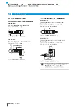
Page 26: ...nder gerade umspritzt konfektioniert M16 8 polig Unterschiedliche Kabell ngen bestellbar z B BKS S232 PU 05 Kabell nge 5 m Bild 12 4 20 66 Steckverbinder BKS S232 PU _ _ BKS S233 PU _ _ Steckverbinder...

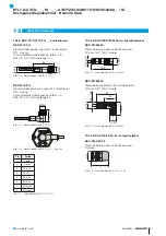
Page 27: ...S116 PU_ _ Abgang Pin Farbe 1 YE gelb 2 GY grau 3 PK rosa 4 RD rot 5 GN gr n 6 BU blau 7 BN braun 8 WH wei Tab 12 1 Pinbelegung BKS S115 116 PU _ _ 12 3 4 BKS S135 S136M 00 frei konfektionierbar BKS S...

Page 28: ...ild 12 12 Vierkantflansch M12 Kontakteinsatz Stecksystem am Beispiel Einbau des Wegaufnehmers in einen Hydraulikzylinder Baureihe ZA10 Material Vierkantflansch Messing vernickelt BTL7 KA00 2 ZA10 PUR...

Page 29: ...version Befestigung A metrisches Befestigungsgewinde M18x1 5 Stabdurchmesser 10 2 mm B metrisches Befestigungsgewinde M18x1 5 O Ring Stabdurchmesser 10 2 mm Y Zollgewinde 3 4 16UNF Stabdurchmesser 10...

Page 30: ...71 10 0 393700787 Tab 14 1 Umrechnungstabelle mm inch 1 inch 25 4 mm inch mm 1 25 4 2 50 8 3 76 2 4 101 6 5 127 6 152 4 7 177 8 8 203 2 9 228 6 10 254 Tab 14 2 Umrechnungstabelle inch mm 14 2 Typensch...

Page 31: ...ny Balluff GmbH Schurwaldstrasse 9 73765 Neuhausen a d F Phone 49 7158 173 370 Fax 49 7158 173 691 service balluff de US Service Center USA Balluff Inc 8125 Holton Drive Florence KY 41042 Phone 859 72...

Page 32: ...User s Guide english BTL7 A C E G_ _ _ M_ _ _ _ A B Y Z 8 S32 S115 S135 S140 BTL7 A C E G_ _ _ M_ _ _ _ A B Y Z 8 KA_ _ FA_ _...

Page 33: ...www balluff com...
Page 34: ...ion guidelines 9 4 2 Preparing for installation 9 4 3 Installing the transducer 10 4 3 1 Installation recommendation for hydraulic cylinders 10 4 4 Electrical connection 11 4 4 1 Connector type S32 ca...

Page 35: ...3 Supply voltage external 23 11 4 Output 23 11 5 Input 23 11 6 Dimensions weights 24 12 Accessories 25 12 1 Magnets 25 12 2 Mounting nut 25 12 3 Connectors and cables 26 12 3 1 BKS S32 S33M 00 freely...

Page 36: ...e immunity EN 61000 6 2 noise immunity EN 61000 6 3 emission EN 61000 6 4 emission and the following product standard EN 61326 2 3 Emission tests RF emission EN 55016 2 3 industrial and residential ar...

Page 37: ...to the work to be done The operator is responsible for ensuring that local safety regulations are observed In particular the operator must take steps to ensure that a defect in the position measuring...

Page 38: ...onnector see Ordering code on page 29 BTL housing Aluminum housing containing the processing electronics Mounting thread We recommend assembling this transducer on the mounting thread BTL7 A B M18 1 5...

Page 39: ...ion The component of the torsional wave which arrives at the beginning of the waveguide is converted by a coil into an electrical signal The travel time of the wave is used to calculate the position D...

Page 40: ...transducer and magnet Horizontal assembly If installing horizontally with nominal lengths 500 mm we recommend tightening the outer rod at the end only possible with 10 2 mm or supporting it Hydraulic...

Page 41: ...detailed solutions is the responsibility of the cylinder manufacturer The sliding element material must be suitable for the appropriate load case medium used and application temperatures E g Torlon Te...

Page 42: ...TL7 _1_ _ BTL7 _5_ _ 6 BU blue GND2 GND2 7 BN brown 20 to 28 V 10 to 30 V 1 Unassigned leads can be connected to the GND on the controller side but not to the shield 2 Reference potential for supply v...

Page 43: ...Connector type S140 S140 Pin Interface BTL7 A B C J K G H E D F Fig 4 12 Pin assignment of S140 view of connector pins of transducer 10 pin circular plug 1 Unassigned leads can be connected to the GN...

Page 44: ...fields The position measuring system is a magnetostrictive system It is important to maintain adequate distance between the transducer cylinder and strong external magnetic fields Cable routing Do no...

Page 45: ...tem manufacturer 1 Check connections for tightness and correct polarity Replace damaged connections 2 Turn on the system 3 Check measured values and adjustable parameters and readjust the transducer i...

Page 46: ...2 Programming input at 20 to 28 V BTL7 _1_ _ or 10 to 30 V BTL7 _5_ _ corresponds to button depressed high active Automatic deactivation If no signals are sent over the programming inputs for approx 1...

Page 47: ...rt value Null point Before After New end value Before After End point 6 3 3 Online setting The detailed procedure for online setting is described on page 21 Setting start and end values while the syst...

Page 48: ...ttons the programming inputs or automatically after 10 min have expired Value table for teach in and adjustment The following examples refer to transducers with 0 to 10 V or 4 to 20 mA output For all...

Page 49: ...Teach in is displayed 4 00 V 12 00 mA Release n Current position value is displayed 5 39 V 9 15 mA 3 Set null point Bring magnet to the new null point 1 04 V 4 82 mA Hold down n for at least 2 s 2 s...

Page 50: ...ition value is displayed 5 39 V 9 15 mA 3 Adjust start value Bring magnet to start position 1 04 V 4 82 mA Hold down n for at least 2 s 2 s 1 Indication for Adjust start value is displayed 0 00 V 4 00...

Page 51: ...19 00 mA Check values The settings for the start value and end value have a mutual effect depending on the measuring position Repeat steps 3 and 4 until the desired values are exactly set 5 Exit adju...

Page 52: ...ge 16 4 84 V 11 74 mA Exit setting do not press a button for at least 15 s The start value is saved the buttons are deactivated 4 84 V 11 74 mA After each calibration procedure you must wait for the l...

Page 53: ...3 s 2 1 5 39 V 10 80 mA Release button 1 s Within 1 s hold down n and d simultaneously for at least 3 s 3 s 1 2 Output indicates error value 10 50 V 3 60 mA Buttons are activated If an error or an in...

Page 54: ...Connector when attached IP 67 Cable IP 683 11 3 Supply voltage external Voltage stabilized4 BTL7 _1_ _ BTL7 _5_ _ 20 to 28 V DC 10 to 30 V DC Ripple d 0 5 Vss Current draw at 24 V DC d 150 mA Inrush...

Page 55: ...8 1 5 or 3 4 16UNF Tightening torque Max 100 Nm BTL7 KA_ _ Cable material PUR cULus 20549 80 C 300 V internal wiring Cable temperature 40 C to 90 C Cable diameter Max 7 mm Permissible bending radius F...

Page 56: ...1013 4R BTL P 1013 4S BTL P 1012 4R magnets includes Spacer 8 mm material polyoxymethylene POM BTL5 P 4500 1 magnet solenoid Weight Approx 90 g Housing Plastic Operating temperature 40 C to 60 C BTL P...

Page 57: ...molded preassembled M16 8 pin Various cable lengths can be ordered e g BKS S232 PU 05 Cable length 5 m Fig 12 4 20 66 Connector type BKS S232 PU _ _ BKS S233 PU _ _ Angled connector molded preassembl...

Page 58: ...type BKS S116 PU_ _ outlet Pin Color 1 YE yellow 2 GY grey 3 PK pink 4 RD red 5 GN green 6 BU blue 7 BN brown 8 WH white Tab 12 1 BKS S115 116 PU _ _ pin assignment 12 3 4 BKS S135 S136M 00 freely con...

Page 59: ...Fig 12 12 Square flange M12 contact insert Plug in system based on the example installing the transducer in a hydraulic cylinder Series ZA10 Square flange material Nickel plated brass BTL7 KA00 2 ZA10...

Page 60: ...M0025 to M1016 A8 B8 Y8 Z8 M0025 to M7620 A B Y Z Rod version fastening A Metric mounting thread M18x1 5 rod diameter 10 2 mm B Metric mounting thread M18x1 5 O ring rod diameter 10 2 mm Y 3 4 16UNF...

Page 61: ...10 0 393700787 Tab 14 1 Conversion table mm to inches 1 inch 25 4 mm inches mm 1 25 4 2 50 8 3 76 2 4 101 6 5 127 6 152 4 7 177 8 8 203 2 9 228 6 10 254 Tab 14 2 Conversion table inches to mm 14 2 Pa...

Page 62: ...any Balluff GmbH Schurwaldstrasse 9 73765 Neuhausen a d F Phone 49 7158 173 370 Fax 49 7158 173 691 service balluff de US Service Center USA Balluff Inc 8125 Holton Drive Florence KY 41042 Phone 859 7...

Reviews: