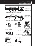
BTL5-P/I/K/L/M_-M/U_ _ _ _-P-S32/KA_ _
Micropulse Linear Transducer
Digital Output / Profile Housing
Read this manual before installing and operating the Micropulse
Transducer.
1.1 Proper application
The BTL5 Micropulse transducer is intended to be installed in a
machine or system. Together with a controller (PLC) or a proces-
sor (BTA) it comprises a position measuring system and may only
be used for this purpose.
Unauthorized modifications and non-permitted usage will result in
the loss of warranty and liability claims.
1.2 Qualified personnel
This guide is intended for specialized personnel who will perform
the installation and setup of the system.
1.3 Use and inspection
The relevant safety regulations must be followed when using the
transducer system. In particular, steps must be taken to ensure
that should the transducer system become defective no hazards to
persons or property can result. This includes the installation of
additional safety limit switches, emergency shutoff switches and
maintaining the permissible ambient conditions.
1.4 Scope
This guide applies to the model
BTL5-P/I/K/L/M...P... Micropulse
transducer.
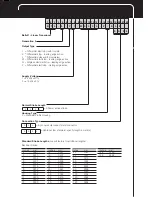
An overview of the various models
can be found in section 6 Versions
(indicated on product label)
on page 7.
1 Safety Advisory
Contents
1
Safety Advisory ............... 2
1.1
Proper application .............. 2
1.2
Qualified personnel ............ 2
1.3
Use and inspection ............ 2
1.4
Scope ................................ 2
2
Function and
Characteristics ............... 3
2.1
Characteristics .................. 3
2.2
Function ............................. 3
2.3
Available stroke lengths
and magnets ..................... 3
3
Installation ..................... 3
3.1
Transducer installation ...... 3
3.2
Floating magnets ............... 4
3.3
Captive magnets ............... 5
4
Wiring .............................. 6
5
Startup ............................. 7
5.1
Check connections ........... 7
5.2
Turning on the system ....... 7
5.3
Check output values ......... 7
5.4
Check functionality ............ 7
5.5
Fault conditions ................. 7
5.6
Noise elimination ............... 7
6
Versions
(indicated on part label) 7
7
Technical Data ............... 8
7.1
Dimensions, weights,
ambient conditions ............ 8
7.2
Supply voltage (external) .... 8
7.3
Control signals .................. 8
7.4
Connection to processor ... 8
7.5
Included in shipment ......... 8
7.6
Magnets (order separately) 8
7.7
Accessories (optional) ....... 8
7.8
Compatible processors
and displays ...................... 8
Note:
For special versions,
which are indicated by an -
SU_ _ _ designation in the
part number, other technical
data may apply (affecting
calibration, wiring, dimen-
sions etc.).
Group 1, Class A
Noise immunity tests:
Static electricity (ESD)
EN 61000-4-2
Severity level 3
Electromagnetic fields (RFI)
EN 61000-4-3
Severity level 3
Fast transients (Burst)
EN 61000-4-4
Severity level 3
Surge
EN 61000-4-5
Severity level 2
Line-induced noise induced by
high-frequency fields
EN 61000-4-6
Severity level 3
Magnetic fields
EN 61000-4-8
Severity level 4
The CE Mark verifies that
our products meet the
requirements of
EC Directive
89/336/EEC (EMC Directive)
and the EMC Law. Testing in our
EMC Laboratory, which is accredited
by DATech for Testing Electromag-
netic Compatibility, has confirmed
that Balluff products meet the EMC
requirements of the following
Generic Standards:
EN 50081-2 (emission)
EN 61000-6-2 (noise immunity)
Emission tests:
RF Emission
EN 55011
The following patents
have been granted in
connection with this
product:
US Patent 5 923 164
Apparatus and Method for
Automatically Tuning the
Gain of an Amplifier
US Patent 5 903 426
Overvoltage Protection
Apparatus for Data
Interface
Summary of Contents for BTL5-P
Page 2: ......

