background image

3

deutsch

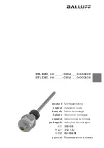
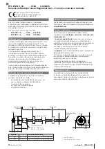
BTL  B/ZNC_ 00- _ _ _ _ -C15A _ _ _0-000S35

Magnetostriktives Positionsmesssystem – Bauform Stab

954925_AA ∙ DE ∙ E22; Änderungen vorbehalten.

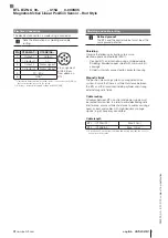
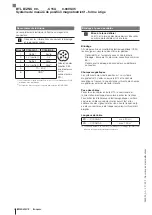
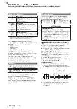
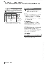
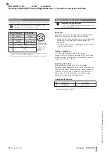
Elektrischer Anschluss

Der elektrische Anschluss ist über eine Steckverbindung 

ausgeführt.

Beachten Sie die Informationen zu Schirmung 

und Kabelverlegung.

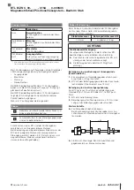
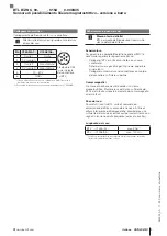
Pin

C15AA/A1…

C15AE/A5…

Pinbelegung S35 

(Draufsicht auf 

Stecker am BTL)

1

Ausgang 1

Ausgang

2

0 V 

(Ausgang 1)

0 V

3

Ausgang 2

nicht belegt

1)

4

0 V 

(Ausgang 2)

nicht belegt

1)

5

10…30 V

6

GND

2)

1) Nicht belegte Adern können steuerungsseitig mit GND verbunden 

werden, aber nicht mit dem Schirm.

2) Bezugspotenzial für Versorgungsspannung und EMV-GND

Schirmung und Kabelverlegung

Definierte Erdung!

BTL und Schaltschrank müssen auf dem glei-

chen Erdungspotenzial liegen.

Schirmung

Zur Gewährleistung der elektromagnetischen Verträglich-

keit (EMV) folgende Hinweise beachten:
–  BTL und Steuerung mit einem geschirmten Kabel 

verbinden.  

Schirmung: Geflecht aus Kupfer-Einzeldrähten, Bede-

ckung mindestens 85 %.


– Schirm im Steckverbinder mit dem Steckergehäuse 

flächig verbinden.

Magnetfelder

Das Positionsmessystem ist ein magnetostriktives System. 

Auf ausreichenden Abstand des BTL und des Aufnahme-

zylinders zu starken externen Magnetfeldern achten.

Kabelverlegung

Alle Kabel zwischen BTL, Steuerung und Stromversorgung 

zugentlastet verlegen. Um elektromagnetische Einstreuun-

gen zu vermeiden, auf ausreichenden Abstand zu stark-

stromführenden Kabeln und Kabeln mit hochfrequenten 

Spannungssignalen (z. B. von Frequenzumrichtern) achten.

Kabellänge

BTL …-C15AA/A1…

max. 30 m

1)

BTL …-C15AE/A5…

max. 100 m

1)

1) Voraussetzung: durch Aufbau, Schirmung und Verlegung keine Einwir-

kung fremder Störfelder.

Summary of Contents for BTL BNC 00 C15A Series

Page 1: ...___0 000S35 BTL ZNC_00 ____ C15A___0 000S35 deutsch Montageanleitung english Installation Guide fran ais Notice de montage italiano Istruzioni di montaggio espa ol Instrucciones de montaje portugu s I...

Page 2: ...em e Verwen dung vor Diese ist nicht zul ssig und f hrt zum Verlust von Gew hrleistungs und Haftungsanspr chen gegen ber dem Hersteller Vern nftigerweise vorhersehbare Fehlanwendung Das Produkt ist f...

Page 3: ...ssl nge Den Stab abst tzen und gegebenenfalls am Ende anschrauben Anzeigeelemente Signal Bedeutung Gr n Normalfunktion Positionsgeber ist innerhalb des Mess bereichs Gelb blinkend 3 Hz Warnung Positio...

Page 4: ...rdungspotenzial liegen Schirmung Zur Gew hrleistung der elektromagnetischen Vertr glich keit EMV folgende Hinweise beachten BTL und Steuerung mit einem geschirmten Kabel verbinden Schirmung Geflecht a...

Page 5: ...Balluff accessories Otherwise there is deemed to be unintended use Unintended use is not permitted and will result in the loss of warranty and liability claims against the manufacturer Reasonably fore...

Page 6: ...ngth of 500 mm Support the rod and if necessary screw on at the end Display elements Signal Meaning Green Normal function Magnet is within the measuring range Yellow flas hing 3 Hz Warning Magnet is o...

Page 7: ...ame ground potential Shielding Observe the following instructions to ensure electromagnetic compatibility EMC Connect BTL and controller using a shielded cable Shielding Braided copper shield with min...

Page 8: ...tion non conforme Celle ci n est pas autoris e et entra ne la perte des droits de garantie et de responsabilit vis vis du fabricant Mauvaise utilisation raisonnablement pr visible Le produit n est pas...

Page 9: ...saire l ments d affichage Signal Signification Vert Fonctionnement normal Le capteur de position est l int rieur de la plage de mesure Jaune cligno tant 3 Hz Avertissement Le capteur de position est l...

Page 10: ...antir la compatibilit lectromagn tique CEM les consignes suivantes doivent tre respect es Relier le BTL et l automate avec un c ble blind Blindage tresse de fils de cuivre couverture minimum 85 Relier...

Page 11: ...so contrario si tratta di uso improprio Questo non consentito e determina la decadenza di qualsiasi garanzia o responsabilit da parte della casa produttrice Utilizzo improprio ragionevolmente prevedib...

Page 12: ...all occorrenza avvitarla all estremit Elementi di visualizzazione Segnale Significato Verde Funzionamento normale Il datore di posizione all interno del campo di misura Luce gialla lampeggiante a 3 Hz...

Page 13: ...terra Schermatura Per garantire la compatibilit elettromagnetica EMC necessario rispettare le seguenti avvertenze Collegare il BTL e l unit di controllo con un cavo schermato Schermatura maglia di si...

Page 14: ...ecuados De lo contrario se trata de un uso indebido Este no se permite y conduce a la p rdida de la garant a y reclamaciones de responsabilidad contra el fabricante Aplicaci n err nea previsible desde...

Page 15: ...apoyar la varilla y dado el caso atornillar en el extremo Elementos indicadores Se al Significado Verde Funcionamiento normal El sensor de posici n est dentro de la zona medible Parpadeando en amaril...

Page 16: ...erra Blindaje Para garantizar la compatibilidad electromagn tica CEM se deben tener en cuenta las siguientes indicaciones Conecte el BTL y el control con un cable blindado Blindaje malla de hilos indi...

Page 17: ...ess rios originais Balluff adequados Caso contr rio ir se configurar uma utiliza o indevida Esta n o permitida e ir resultar na perda dos direitos de garantia e de responsabilidade perante o fabricant...

Page 18: ...fus la na extremidade Elementos indicadores Sinal Significado Verde Funcionamento normal Encoder de posi o se encontra dentro da faixa de medi o Piscando em amarelo 3 Hz Aviso Encoder de posi o se enc...

Page 19: ...cial terra Blindagem Para garantir a compatibilidade eletromagn tica EMV devem ser observadas as seguintes orienta es conecte o BTL e o comando com um cabo blindado Blindagem malha de cobre cobertura...

Page 20: ...CE 10 2 25 0 5 25 34 60 X 41 45 12 M16 BTL B M18 1 5 BTL Z 3 4 16UNF 2 X BTL _NCA 30 1 mm M4 4 5 BTL _NCE 2 0 04 M4 4 5 1 2 1 1 S35 BTL BTL BNC_00 ____ C15A___0 000S35 BTL ZNC_00 ____ C15A___0 000S35...

Page 21: ...luff com 2 BTL B ZNC_00 ____ C15A___0 000S35 D2 10 2 mm 13 mm BTL BTL O 1 O 2 BTL 75 Nm BTL M18 1 5 ISO 3 4 16UNF SAE 1 BTL 2 75 Nm 65 mm 65 500 mm 3 Hz 1 Hz 3 Hz 1 1 1 2 LED 1 FMM LED 1 2 2 FMM LED B...

Page 22: ...3 BTL B ZNC_00 ____ C15A___0 000S35 954925_AA ZH E22 C15AA A1 C15AE A5 S35 BTL 1 1 2 0 V 1 0V 3 2 1 4 0 V 2 1 5 10 30 V 6 2 1 2 EMC GND BTL EMC BTL 85 BTL BTL BTL C15AA A1 30 m1 BTL C15AE A5 100 m1 1...

Page 23: ...000S35 CE EU 10 2 25 0 5 25 34 60 X 41 45 12 M16 BTL B M18 1 5 BTL Z 3 4 16UNF 2 X BTL _NCA 30 1 mm M4 4 5 BTL _NCE 2 0 04 M4 4 5 1 2 1 1 S35 BTL BTL BNC_00 ____ C15A___0 000S35 BTL ZNC_00 ____ C15A__...

Page 24: ...5A___0 000S35 D2 10 2 mm 13 mm BTL BTL O 1 O 2 BTL 75 Nm BTL M18 1 5 ISO 3 4 16UNF SAE 1 BTL 2 75 Nm 65 mm 65 500 mm 3 Hz 1 Hz 3 Hz 1 1 2 1 2 LED 1 FMM Flexible Magnet Mode LED 1 2 2 FMM Flexible Magn...

Page 25: ...com 3 BTL B ZNC_00 ____ C15A___0 000S35 954925_AA KO E22 C15AA A1 C15AE A5 S35 BTL 1 1 2 0 V 1 0V 3 2 1 4 0 V 2 1 5 10 30 V 6 GND2 1 GND 2 EWV GND BTL EMV BTL 85 BTL BTL BTL C15AA A1 30 m1 BTL C15AE...

Page 26: ...E EU 10 2 25 0 5 25 34 60 X 41 45 12 M16 BTL B M18 1 5 BTL Z 3 4 16UNF 2 X BTL _NCA 30 1 mm M4 4 5 BTL _NCE 2 0 04 M4 4 5 1 2 1 1 S35 BTL BTL BNC_00 ____ C15A___0 000S35 BTL ZNC_00 ____ C15A___0 000S3...

Page 27: ...com 2 BTL B ZNC_00 ____ C15A___0 000S35 D2 10 2 mm 13 mm BTL BTL O 1 O 2 BTL 75 Nm BTL M18 1 5 ISO 3 4 16UNF SAE 1 BTL 2 75 Nm 65 mm 65 500 mm 3 Hz 1 Hz 3 Hz 1 1 2 2 1 2 LED FMM 1 LED 1 2 FMM 2 LED 2...

Page 28: ...L B ZNC_00 ____ C15A___0 000S35 954925_AA JA E22 C15AA A1 C15AE A5 S35 BTL 1 1 2 0 V 1 0 V 3 2 1 4 0 V 2 1 5 10 30 V 6 GND2 1 GND 2 EMC GND BTL EMC BTL 85 BTL BTL BTL C15AA A1 30 m1 BTL C15AE A5 100 m...

Page 29: ..._0 000S35 CE EC 10 2 25 0 5 25 34 60 X 41 45 12 M16 BTL B M18 1 5 BTL Z 3 4 16UNF 2 X BTL _NCA 30 1 M4 4 5 BTL _NCE 2 0 04 M4 4 5 1 2 1 1 S35 BTL BTL BNC_00 ____ C15A___0 000S35 BTL ZNC_00 ____ C15A__...

Page 30: ...2 BTL B ZNC_00 ____ C15A___0 000S35 D2 10 2 13 BTL BTL 1 2 BTL 75 BTL M18 1 5 ISO 3 4 16UNF SAE 1 BTL 2 75 65 65 500 3 1 3 1 1 2 1 2 FMM Flexible Magnet Mode 1 1 2 FMM Flexible Magnet Mode 2 2 BTL BTL...

Page 31: ...luff com 3 BTL B ZNC_00 ____ C15A___0 000S35 954925_AA RU E22 C15AA A1 C15AE A5 S35 BTL 1 1 2 0 1 0 3 2 1 4 0 2 1 5 10 30 6 GND2 1 GND 2 EMV GND BTL EMV BTL 85 BTL BTL BTL C15AA A1 30 1 BTL C15AE A5 1...

Page 32: ...hengshan Rd 8F Building A Yunding International Commercial Plaza 200125 Pudong Shanghai Phone 86 400 820 0016 Fax 86 400 920 2622 service cn balluff com cn DACH Service Center Germany Balluff GmbH Sch...

Reviews: