background image

www.balluff.com

9

español

5.2 

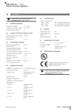
Determinar la posición de émbolo con una 

barra magnética

Con una pequeña barra magnética polarizada axialmente, 

es posible determinar de forma muy sencilla el recorrido de 

pasada del imán cilíndrico y, de este modo, la posición 

ideal del sensor.

Determinar la posición de montaje
1. 

Aplicar la barra magnética sobre la pared lateral o en la 

ranura del cilindro de tal modo que atraiga al imán.

Bild 5-4:  Aplicar la barra magnética

2. 

Desplegar la barra cilíndrica por completo.


El imán se mueve al mismo tiempo.

Bild 5-5:  Desplegar la barra cilíndrica

3. 

Marcar la posición del imán (centro del imán).

Bild 5-6:  Marcar la posición de imán

5


Montaje y conexión (continuación)

4. 

Replegar la barra cilíndrica por completo.


El imán se mueve al mismo tiempo.

Bild 5-7:  Replegar la barra cilíndrica

5. 

Marcar la posición del imán (centro del imán).

Bild 5-8:  Marcar la posición de imán

6. 

Montar el sensor en el centro entre las dos marcas 

(muesca del sensor).

Bild 5-9:  Montar el sensor

BMF 423K-AA _ _ -C-2-…

Sensores de campo magnético

Summary of Contents for BMF 423K-AA C-2 Series

Page 1: ...BMF 423K AA_ _ C 2 deutsch Betriebsanleitung english User s Guide fran ais Notice d utilisation italiano Manuale d uso espa ol Manual de instrucciones portugu s Manual de Instru es...

Page 2: ...www balluff com...

Page 3: ...BMF 423K AA _ _ C 2 Betriebsanleitung deutsch...

Page 4: ...www balluff com...

Page 5: ...4 1 Funktion 7 4 2 Anzeigeelemente 7 4 3 Kabelbedruckung 7 5 Einbau und Anschluss 8 5 1 Sensor montieren 8 5 2 Kolbenposition mit einem Stabmagnet bestimmen 9 5 3 Elektrischer Anschluss 10 6 Inbetrie...

Page 6: ...nden Dokumenten Datenblatt Konformit tserkl rung Entsorgung 1 3 Verwendete Symbole und Konventionen Einzelne Handlungsanweisungen werden durch ein vorangestelltes Dreieck angezeigt Handlungsanweisung...

Page 7: ...gesetzt werden in sicherheitsgerichteten Anwendungen in denen die Personensicherheit von der Ger tefunktion abh ngt in explosionsgef hrdeten Bereichen im Lebensmittelbereich 2 3 Allgemeine Sicherheits...

Page 8: ...nes Zubeh r finden Sie unter www balluff com auf der Produktseite 3 2 Transport Produkt in Originalverpackung bis zum Verwendungs ort transportieren 3 3 Lagerbedingungen Produkt in Originalverpackung...

Page 9: ...szustand Farbe Zustand Gelb On Schaltpunkt ist aktiv Off Schaltpunkt ist inaktiv Tab 4 1 LED Anzeige 4 Produktbeschreibung 4 3 Kabelbedruckung Bild 4 2 Bestellcode Typ Kabelbedruckung Beispiel Bild 4...

Page 10: ...C Nut Bild 5 1 C Nut 3 6 3 3 8 4 2 3 3 2 4 2 2 1 Sensor einsetzen Variante A Variante B Bild 5 2 Montage BMF 203K in zwei Varianten 2 Sensor festziehen Schl ssel 0 9 Anzugsdrehmoment 0 07 Nm Bild 5 3...

Page 11: ...tabmagnet aufbringen 2 Zylinderstange komplett ausziehen Der Magnet bewegt sich mit Bild 5 5 Zylinderstange ausziehen 3 Position des Magneten markieren Mitte des Magneten Bild 5 6 Magnetposition marki...

Page 12: ...Braun UB 24 V Pin 2 Wei nicht belegt1 Pin 3 Blau UB GND Bezugspotenzial Pin 4 Schwarz Sensorausgang 1 1 bei BMF SA95 Sensorausgang 2 Tab 5 1 Pinbelegung Der Sensor verf gt ber einen berlastschutz Nach...

Page 13: ...ten 1 Anschl sse auf festen Sitz und richtige Polung pr fen Besch digte Anschl sse tauschen 2 System einschalten 3 Messwerte und einstellbare Parameter pr fen und ggf den Sensor neu einstellen Dabei E...

Page 14: ...tsch 7 1 Entsorgung Befolgen Sie die nationalen Vorschriften zur Entsor gung Weitere Informationen finden Sie unter www balluff com auf der Produktseite 7 Entsorgung BMF 423K AA _ _ C 2 Magnetfeld Sen...

Page 15: ...ypenschl ssel auf Seite 14 Kabeldurchmesser D 2 4 mm Kurzschlusschutz ja Verpolungssicher ja Verbindung P0 S49 M8x1 Stecker 3 polig P0 S4 M12x1 Stecker 3 polig P0 S75 M 8x1 Stecker 4 polig SA95 _ _ S4...

Page 16: ...bel 2 m P0 05 PUR Kabel 5 m P0 S49 00 3 PUR Kabel 0 3 m mit M8 Stecker 3 polig P0 S4 00 3 PUR Kabel 0 3 m mit M12 Stecker 4 polig P0 S75 00 3 PUR Kabel 0 3 m mit M8 Stecker 4 polig Bestellbeispiel BMF...

Page 17: ...BMF 423K AA _ _ C 2 User s Guide english...

Page 18: ...www balluff com...

Page 19: ...n 7 4 2 Display elements 7 4 3 Cable imprint 7 5 Installation and connection 8 5 1 Mounting the sensor 8 5 2 Determining the piston position with a rod magnet 9 5 3 Electrical connection 10 6 Startup...

Page 20: ...duct page e g in the following documents Data sheet Declaration of Conformity Disposal 1 3 Symbols and conventions Individual action instructions are indicated by a preceding triangle Instruction 1 Ac...

Page 21: ...not be used there In safety oriented applications in which personal safety depends on the device function In explosive atmospheres In food applications 2 3 General safety notes Activities such as ins...

Page 22: ...parately Recommended accessories can be found at www balluff com on the product page 3 2 Transport Transport product to location of use in original packaging 3 3 Storage conditions Store product in or...

Page 23: ...g state Color State Yellow On Switching point is active Off Switching point is inactive Tab 4 1 LED display 4 Product description 4 3 Cable imprint Fig 4 2 Order code Type Cable imprint example Fig 4...

Page 24: ...ion Fig 5 1 C slot 3 6 3 3 8 4 2 3 3 2 4 2 2 1 Insert the sensor Variant A Variant B Fig 5 2 Installation of BMF 203K in two versions 2 Tighten down sensor 0 9 wrench tightening torque 0 07 Nm Fig 5 3...

Page 25: ...4 Place bar magnet in place 2 Extend the cylinder rod completely The magnet will move with it Fig 5 5 Tighten cylinder rod 3 Mark the position of the magnet center of the magnet Fig 5 6 Mark magnet po...

Page 26: ...UB 24 V Pin 2 White Not used1 Pin 3 Blue UB GND reference potential Pin 4 Black Sensor output 1 1 for BMF SA95 sensor output 2 Tab 5 1 Pin assignment The sensor features overload protection After the...

Page 27: ...connections for tightness and correct polarity Replace damaged connections 2 Turn on the system 3 Check measured values and adjustable parameters and readjust the sensor if necessary Check spacing ov...

Page 28: ...12 english 7 1 Disposal Observe the national regulations for disposal Additional information can be found at www balluff com on the product page 7 Disposal BMF 423K AA _ _ C 2 Magnetic Field Sensors...

Page 29: ...see Type code on page 14 Cable diameter D 2 4 mm Short circuit protected yes Polarity reversal protected yes Connection P0 S49 M8x1 male 3 pin P0 S4 M12x1 male 3 pin P0 S75 M 8x1 male 4 pin SA95 _ _ S...

Page 30: ...P0 02 PUR cable 2 m P0 05 PUR cable 5 m P0 S49 00 3 PUR cable 0 3 m with M8 male 3 pin P0 S4 00 3 PUR cable 0 3 m with M12 male 4 pin P0 S75 00 3 PUR cable 0 3 m with M8 male 4 pin Ordering example BM...

Page 31: ...BMF 423K AA _ _ C 2 Notice d utilisation fran ais...

Page 32: ...www balluff com...

Page 33: ...ents d affichage 7 4 3 Marquage des c bles 7 5 Montage et raccordement 8 5 1 Montage du capteur 8 5 2 D termination de la position de piston l aide d un barreau aimant 9 5 3 Raccordement lectrique 10...

Page 34: ...roduit du site www balluff com p ex dans les documents suivants Fiche technique D claration de conformit limination 1 3 Symboles et conventions utilis s Les instructions sp cifiques sont pr c d es d u...

Page 35: ...re dans des applications orient es s curit dont la s curit des personnes d pend de la fonction de l appareil dans des zones explosibles dans le domaine alimentaire 2 3 Consignes g n rales de s curit L...

Page 36: ...verez les accessoires conseill s sous www balluff com sur la page produit 3 2 Transport Transporter le produit dans son emballage d origine jusqu au lieu d utilisation 3 3 Conditions de stockage Stock...

Page 37: ...tat Jaune Allum e Le point d action est actif teinte Le point d action est inactif Tab 4 1 Affichage LED 4 Description du produit 4 3 Marquage des c bles Fig 4 2 Symbolisation commerciale Type Marqua...

Page 38: ...ig 5 1 Rainure en C 3 6 3 3 8 4 2 3 3 2 4 2 2 1 Introduction du capteur Version A Version B Fig 5 2 Montage du BMF 203K en deux versions 2 Serrage du capteur cl de 0 9 mm couple de serrage 0 07 Nm Fig...

Page 39: ...ttir Fig 5 4 Installer le barreau aimant 2 Extraire compl tement la tige du v rin L aimant se d place avec Fig 5 5 Extraire la tige du v rin 3 Marquer la position de l aimant centre de l aimant Fig 5...

Page 40: ...V Pin 2 Blanc non utilis 1 Pin 3 Bleu UB GND potentiel de r f rence Pin 4 Noir Sortie capteur 1 1 avec BMF SA95 sortie capteur 2 Tab 5 1 Affectation des broches Le capteur dispose d une protection co...

Page 41: ...on et la polarit des raccordements Remplacer les raccordements endommag s 2 Mettre le syst me en marche 3 V rifier les valeurs mesur es et les param tres r glables et le cas ch ant proc der un nouveau...

Page 42: ...nation Pour l limination des d chets se conformer aux dispositions nationales Vous trouverez des informations compl mentaires sous www balluff com sur la page produit 7 limination BMF 423K AA _ _ C 2...

Page 43: ...le D 2 4 mm Protection contre les courts circuits oui Protection contre l inversion de polarit oui Connexion P0 S49 Connecteur m le M8x1 3 p les P0 S4 Connecteur m le M12x1 3 p les P0 S75 Connecteur m...

Page 44: ...PUR 2 m P0 05 C ble PUR 5 m P0 S49 00 3 C ble PUR 0 3 m avec connecteur m le M8 3 p les P0 S4 00 3 C ble PUR 0 3 m avec connecteur m le M12 4 p les P0 S75 00 3 C ble PUR 0 3 m avec connecteur m le M8...

Page 45: ...BMF 423K AA _ _ C 2 Manuale d uso italiano...

Page 46: ...www balluff com...

Page 47: ...zazione 7 4 3 Siglatura sul cavo 7 5 Montaggio e collegamento 8 5 1 Montaggio del sensore 8 5 2 Determinare posizione del pistone tramite un magnete a stelo 9 5 3 Collegamento elettrico 10 6 Messa in...

Page 48: ...ti Scheda tecnica Dichiarazione di Conformit Smaltimento 1 3 Simboli e segni utilizzati Le singole istruzioni operative sono precedute da un triangolo Istruzione operativa 1 Le sequenze operative veng...

Page 49: ...e dipenda dal funzionamento dell apparecchio in aree a rischio di esplosione in ambito alimentare 2 3 Indicazioni di sicurezza generali Attivit quali montaggio collegamento e messa in funzione andrann...

Page 50: ...onsigliati consultare l indirizzo www balluff com pagina Prodotti 3 2 Trasporto Trasportare il prodotto nella confezione originale fino al luogo di utilizzo 3 3 Condizioni di magazzinaggio Conservare...

Page 51: ...nzionamento Colore Stato Giallo On Punto di commutazione attivo Off Punto di commutazione inattivo Tab 4 1 Indicatore LED 4 Descrizione del prodotto 4 3 Siglatura sul cavo Fig 4 2 Codice d ordine Tipo...

Page 52: ...Fig 5 1 Scanalatura a C 3 6 3 3 8 4 2 3 3 2 4 2 2 1 Inserire il sensore Variante A Variante B Fig 5 2 Montaggio BMF 203K in due varianti 2 Serrare il sensore chiave 0 9 coppia di serraggio 0 07 Nm Fi...

Page 53: ...a stelo 2 Estrarre completamente la biella del cilindro Il magnete si sposter con essa Fig 5 5 Estrazione della biella del cilindro 3 Contrassegnare la posizione del magnete centro del magnete Fig 5...

Page 54: ...4 V Pin 2 Bianco non utilizzato1 Pin 3 Blu UB GND potenziale di riferimento Pin 4 Nero Uscita sensore 1 1 Per BMF SA95 uscita sensore 2 Tab 5 1 Disposizione pin Il sensore dotato di protezione da sovr...

Page 55: ...nte e che la loro polarit sia corretta Sostituire i collegamenti danneggiati 2 Attivare il sistema 3 Controllare i valori misurati e i parametri regolabili e all occorrenza reimpostare il sensore Dura...

Page 56: ...1 Smaltimento Seguire le disposizioni nazionali per lo smaltimento Ulteriori informazioni sono disponibili all indirizzo www balluff com pagina Prodotti 7 Smaltimento BMF 423K AA _ _ C 2 Sensori di ca...

Page 57: ...genda codici di identificazione a pag 14 Diametro cavo D 2 4 mm Protezione dai cortocircuiti s Protezione inversione di polarit s Collegamento P0 S49 Connettore M8x1 a 3 poli P0 S4 Connettore M12x1 a...

Page 58: ...Collegamento elettrico P0 02 cavo PUR 2 m P0 05 cavo PUR 5 m P0 S49 00 3 cavo PUR 0 3 m con connettore M8 a 3 poli P0 S4 00 3 cavo PUR 0 3 m con connettore M12 a 4 poli P0 S75 00 3 cavo PUR 0 3 m con...

Page 59: ...BMF 423K AA _ _ C 2 Manual de instrucciones espa ol...

Page 60: ...www balluff com...

Page 61: ...7 4 2 Elementos indicadores 7 4 3 Impresi n de cable 7 5 Montaje y conexi n 8 5 1 Montar el sensor 8 5 2 Determinar la posici n de mbolo con una barra magn tica 9 5 3 Conexi n el ctrica 10 6 Puesta en...

Page 62: ...los siguientes documentos Hoja de datos Declaraci n de conformidad Eliminaci n de desechos 1 3 S mbolos y convenciones utilizados Cada una de las instrucciones va precedida de un tri ngulo Instrucci...

Page 63: ...do En aplicaciones relacionadas con la seguridad en las que la seguridad personal depende de la funci n del aparato En zonas con riesgo de explosi n En el sector alimentario 2 3 Indicaciones de seguri...

Page 64: ...ios recomendados en www balluff com en la p gina del producto 3 2 Transporte Transportar el producto en el embalaje original al lugar de uso 3 3 Condiciones de almacenamiento Almacenar el producto en...

Page 65: ...do Amarillo Encendido El punto de conmutaci n est activo Apagado El punto de conmutaci n est inactivo Tab 4 1 Indicador LED 4 Descripci n de producto 4 3 Impresi n de cable Fig 4 2 C digo de pedido Ti...

Page 66: ...de la ranura en C Fig 5 1 Ranura en C 3 6 3 3 8 4 2 3 3 2 4 2 2 1 Insertar el sensor Variante A Variante B Bild 5 2 Montaje BMF 203K en dos variantes 2 Apretar el sensor llave 0 9 Par de apriete 0 07...

Page 67: ...n Bild 5 4 Aplicar la barra magn tica 2 Desplegar la barra cil ndrica por completo El im n se mueve al mismo tiempo Bild 5 5 Desplegar la barra cil ndrica 3 Marcar la posici n del im n centro del im...

Page 68: ...UB 24 V Pin 2 Blanco No se utiliza1 Pin 3 Azul UB GND potencial de referencia Pin 4 Negro Salida de sensor 1 1 Con BMF SA95 salida de sensor 2 Tab 5 1 Asignaci n de pines El sensor dispone de una prot...

Page 69: ...firmemente y tengan la polaridad correcta Sustituya las conexiones da adas 2 Conecte el sistema 3 Compruebe los valores de medici n y los par metros ajustables y en caso necesario reajuste el sensor C...

Page 70: ...de desechos 7 1 Eliminaci n de desechos Respete las normas nacionales sobre eliminaci n de desechos Encontrar informaci n detallada en www balluff com en la p gina del producto BMF 423K AA _ _ C 2 Sen...

Page 71: ...ro del cable D 2 4 mm Protecci n contra cortocircuitos S Protecci n contra polaridad inversa S Conexi n P0 S49 Conector macho M8x1 3 polos P0 S4 Conector macho M12x1 3 polos P0 S75 Conector macho M 8x...

Page 72: ...02 Cable de PUR 2 m P0 05 Cable de PUR 5 m P0 S49 00 3 Cable de PUR 0 3 m con conector M8 3 polos P0 S4 00 3 Cable de PUR 0 3 m con conector M12 4 polos P0 S75 00 3 Cable de PUR 0 3 m con conector M8...

Page 73: ...BMF 423K AA _ _ C 2 Manual de Instru es portugu s...

Page 74: ...www balluff com...

Page 75: ...do produto 7 4 1 Fun o 7 4 2 Elementos indicadores 7 4 3 Marca o do cabo 7 5 Montagem e acoplamento 8 5 1 Montar sensor 8 5 2 Determinar a posi o do pist o com uma barra magn tica 9 5 3 Conex o el tri...

Page 76: ...s Declara o de conformidade Elimina o 1 3 S mbolos e conven es empregados Cada instru o de procedimento precedida por um tri ngulo indicativo Instru o de procedimento 1 As instru es de procedimento ap...

Page 77: ...m finalidades de seguran a nas quais a seguran a de pessoas dependa do funcionamento do aparelho em reas com risco de explos o na ind stria aliment cia 2 3 Avisos gerais de seguran a Somente pessoas e...

Page 78: ...Complementos recomendados em www balluff com na p gina do produto 3 2 Transporte Transportar o produto em sua embalagem original at o local de uso 3 3 Condi es de armazenamento Armazenar o produto na...

Page 79: ...marelo Ligado O ponto de comuta o est ativo Desligado O ponto de comuta o n o est ativo Tab 4 1 L mpada LED 4 Descri o do produto 4 3 Marca o do cabo Fig 4 2 N mero do pedido Modelo Marca o do cabo ex...

Page 80: ...anhura C Fig 5 1 Ranhura C 3 6 3 3 8 4 2 3 3 2 4 2 2 1 Aplicar sensor Variante A Variante B Fig 5 2 Montagem do BMF 203K em duas variantes 2 Apertar o sensor chave 0 9 torque de aperto 0 07 Nm Fig 5 3...

Page 81: ...orma que o m seja atra do Fig 5 4 Colocar a barra magn tica 2 Extrair completamente a haste do cilindro O m n o se move Fig 5 5 Extrair a haste do cilindro 3 Marcar a posi o do m centro do m Fig 5 6 M...

Page 82: ...V Pino 2 Branco n o ocupado1 Pino 3 Azul UB GND potencial de refer ncia Pino 4 Preto Sa da do sensor 1 1 para BMF SA95 sa da do sensor 2 Tab 5 1 Posi o dos pinos O sensor possui um dispositivo de prot...

Page 83: ...lamentos est o apertados com firmeza e se a polaridade est correta Substituir os acoplamentos danificados 2 Conectar o sistema 3 Teste os valores de medi o e par metros configur veis e se necess rio a...

Page 84: ...2 portugu s 7 1 Elimina o Cumpra as normas nacionais de elimina o Mais informa es sobre este produto em www balluff com na p gina do produto 7 Elimina o BMF 423K AA _ _ C 2 Sensores de campo magn tico...

Page 85: ...to do cabo consultar Chave de tipos na p gina 14 Di metro do cabo D 2 4 mm Prote o de curto circuito sim Prote o contra invers o de polaridade sim Conex o P0 S49 Plugue M8x1 3 polos P0 S4 Plugue M12x1...

Page 86: ...R 2 m P0 05 Cabo de PUR 5 m P0 S49 00 3 Cabo de PUR 0 3 m com plugue M8 3 polos P0 S4 00 3 Cabo de PUR 0 3 m com plugue M12 4 polos P0 S75 00 3 Cabo de PUR 0 3 m com plugue M8 4 polos Exemplo de pedid...

Page 87: ...BMF 423K AA _ _ C 2...

Page 88: ...www balluff com...

Page 89: ...2 4 1 3 4 1 4 4 2 5 2 1 5 2 2 5 2 3 5 3 6 3 1 6 3 2 6 3 3 6 4 7 4 1 7 4 2 7 4 3 7 5 8 5 1 8 5 2 9 5 3 10 6 11 6 1 11 6 2 11 6 3 11 7 12 7 1 12 8 13 8 1 13 8 2 13 8 3 13 8 4 13 8 5 13 8 6 13 8 7 13 8...

Page 90: ...4 1 1 BMF 423K AA_ _ C 2 14 BMF 423K AAPS C 2 PNP BMF 423K AAPO C 2 PNP BMF 423K AANS C 2 NPN Copyright 2023 Balluff GmbH 1 2 www balluff com 1 3 1 1 1 2 2 23 0x 0x12AB 1 4 1 BMF 423K AA _ _ C 2...

Page 91: ...www balluff com 5 2 1 BMF 423K 2 2 2 3 2 BMF 423K AA _ _ C 2...

Page 92: ...6 3 1 www balluff com 3 2 3 3 13 3 BMF 423K AA _ _ C 2...

Page 93: ...D 4 1 LED 4 4 3 4 2 4 1 49 M12x1 15 49 M12x1 15 M8x1 11 36 5 3 6 5 24 D M2 1 LED 2 9 L 39 10 M8x1 L L L L P0 S49 00 3 P0 02 05 L 0 3 m L 2 5 m L 0 3 m L 0 3 m L 0 3 m P0 S4 00 3 SA95 P0 S4 00 3 SA95 P...

Page 94: ...8 5 1 4 1 7 C 5 1 C 3 6 3 3 8 4 2 3 3 2 4 2 2 1 A B 5 2 BMF 203K 2 0 9 0 07 Nm 5 3 5 BMF 423K AA _ _ C 2...

Page 95: ...www balluff com 9 5 2 1 5 4 2 5 5 3 5 6 5 4 5 7 5 5 8 6 5 9 BMF 423K AA _ _ C 2...

Page 96: ...10 5 5 3 S4 M12 4 S49 M8 3 S75 M8 4 5 10 1 UB 24 V 2 1 3 UB GND 4 1 1 BMF SA95 2 5 1 BMF PS M BK BN BU BMF P0 BMF NS M BK BN BU BMF NS SA95 BMF 423K AA _ _ C 2...

Page 97: ...www balluff com 11 6 1 1 2 3 BMF 6 2 6 3 6 BMF 423K AA _ _ C 2...

Page 98: ...12 7 1 www balluff com 7 BMF 423K AA _ _ C 2...

Page 99: ...DC 100 mA 75 V DC Ub 10 30 V DC 1 F Io 2 mA 500 Hz 1 V 8 4 3 x 0 07 mm2 14 D 2 4 mm P0 S49 M8x1 3 P0 S4 M12x1 3 P0 S75 M 8x1 4 SA95 _ _ S4 M12x1 4 P0 00X 8 5 BMF AAPS PNP NO BMF AAPO PNP NC BMF AANS...

Page 100: ...0 S4 00 3 423K C PS PNP PO PNP NS NPN P0 02 PUR 2 m P0 05 PUR 5 m P0 S49 00 3 PUR 0 3 m M8 3 P0 S4 00 3 PUR 0 3 m M12 4 P0 S75 00 3 PUR 0 3 m M8 4 BMF 423K AANS C 2 SA95 P0 S4 BMF 4 7 950735_AA ZH K23...

Page 101: ...BMF 423K AA _ _ C 2...

Page 102: ...www balluff com...

Page 103: ...2 4 1 3 4 1 4 4 2 5 2 1 5 2 2 5 2 3 5 3 6 3 1 6 3 2 6 3 3 6 4 7 4 1 7 4 2 7 4 3 7 5 8 5 1 8 5 2 9 5 3 10 6 11 6 1 11 6 2 11 6 3 11 7 12 7 1 12 8 13 8 1 13 8 2 13 8 3 13 8 4 13 8 5 13 8 6 13 8 7 13 8...

Page 104: ...MF 423K AA_ _ C 2 14 BMF 423K AAPS C 2 PNP BMF 423K AAPO C 2 PNP BMF 423K AANS C 2 NPN Copyright 2023 Balluff GmbH Balluff GmbH 1 2 www balluff com 1 3 1 1 1 2 2 10 23 16 0x 0x12AB 1 4 1 BMF 423K AA _...

Page 105: ...www balluff com 5 2 1 BMF 423K Balluff 2 2 2 3 2 BMF 423K AA _ _ C 2...

Page 106: ...6 3 1 www balluff com 3 2 3 3 13 3 BMF 423K AA _ _ C 2...

Page 107: ...ED ON OFF 4 1 LED 4 4 3 4 2 4 1 49 M12x1 15 49 M12x1 15 M8x1 11 36 5 3 6 5 24 D M2 1 LED 2 9 L 39 10 M8x1 L L L L P0 S49 00 3 P0 02 05 0 3 m 2 5 m 0 3 m 0 3 m 0 3 m P0 S4 00 3 SA95 P0 S4 00 3 SA95 P0...

Page 108: ...8 5 1 4 1 7 C 5 1 C 3 6 3 3 8 4 2 3 3 2 4 2 2 1 A B 5 2 BMF 203K 2 2 0 9 0 07 Nm 5 3 5 BMF 423K AA _ _ C 2...

Page 109: ...www balluff com 9 5 2 1 5 4 2 5 5 3 5 6 5 4 5 7 5 5 8 6 5 9 BMF 423K AA _ _ C 2...

Page 110: ...10 5 5 3 S4 M12 4 S49 M8 3 S75 M8 4 5 10 1 UB 24 V 2 1 3 UB GND 4 1 1 BMF SA95 2 5 1 BMF PS M BK BN BU BMF P0 BMF NS M BK BN BU BMF NS SA95 BMF 423K AA _ _ C 2...

Page 111: ...www balluff com 11 6 1 1 2 3 BMF 6 2 6 3 6 BMF 423K AA _ _ C 2...

Page 112: ...12 7 1 www balluff com 7 BMF 423K AA _ _ C 2...

Page 113: ...DC 100 mA 75 V DC Ub 10 30 V DC 1 F Io 2 mA 500 Hz 1 V 8 4 3 0 07 mm2 14 D 2 4 mm P0 S49 M8x1 3 P0 S4 M12x1 3 P0 S75 M 8x1 4 SA95 _ _ S4 M12x1 4 P0 00X 8 5 BMF AAPS PNP NO BMF AAPO PNP NC BMF AANS NP...

Page 114: ...P0 S4 00 3 423K C PS PNP PO PNP NS NPN P0 02 PUR 2 m P0 05 PUR 5 m P0 S49 00 3 PUR 0 3 m M8 3 P0 S4 00 3 PUR 0 3 m M12 4 P0 S75 00 3 PUR 0 3 m M8 4 BMF 423K AANS C 2 SA95 P0 S4 2 4 7 950735_AA JA K23...

Page 115: ......
Page 116: ...uidling A Yunding International Commercial Plaza 200125 Pudong Shanghai China Headquarters und Technical Service Hub Region EMEA Balluff GmbH Schurwaldstrasse 9 73765 Neuhausen a d F Germany Technical...

Reviews: