background image

 
Operating Manual 
Inductive Positioning System BIP AD0-B014-01-EP02


No. 872877 EN E16 


Installation 


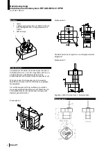
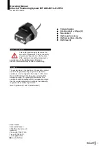
1.  Pushbutton 
2.  2 screws for example DIN 912 M4x14 (not 

included). Torque of the fastening screws, max. 
0.5Nm 

3.  LED 

– indicator 

 
         1              2 
 

4. 


5.   
6.   
7.   
8.   
9.   
10.   
11.   
12.   
13.   
14.   
15.   

                         3 


Installation notices


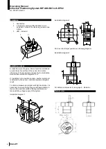
A metal-free area of approx. 5mm should be maintained 
around the active surface of the sensor to minimize 
influencing of the measurement signal by the installation 
material (see installation diagrams 1+2). 
 
If, in addition to the position encoder, another metal part 
is detected by the sensor, invalid measurement signals 
result. 
 
To obtain a measurement signal with high resolution, it is 
necessary to ensure that cables are laid appropriately in 
the machine and that suitable filtering measures are 
taken with the voltage supply of the system. 
 
Installation diagram 1 


Installation diagram 2 


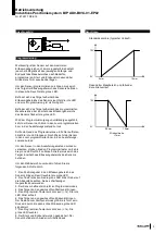
For the correct target position see following diagram   
 
Installation diagram 3 


For details on dimension D, see page 4 - Remarks 

 
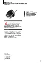
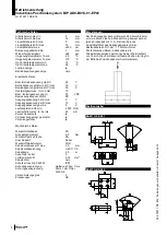
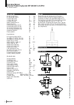
Product view


Summary of Contents for BIP AD0-B014-01-EP02

Page 1: ...rhalb des eingelernten Messbereiches und gibt diese als Spannungssignal im Bereich 0 10V aus Die rote LED signalisiert dabei das Verlassen des Messbereiches Die gr ne LED leuchtet wenn sich der Positi...

Page 2: ...ssung des Messsignals durch das Einbaumaterial zu minimieren siehe Einbauskizze 1 2 Wird neben dem Positionsgeber noch ein weiteres Metallteil vom Sensor erkannt f hrt dies zu ung ltigen Messsignalen...

Page 3: ...auftreten blinkt die rote LED langsam Nach 20s kehrt der Sensor in den zuvor programmierten bzw in den Auslieferungs zustand zur ck Um den Sensor in den Auslieferungszustand zur ck zu versetzen dr cke...

Page 4: ...0 mA Kurzschlussschutz ja Vertauschungsm gl gesch tzt ja Verpolungssicher ja Mechanische Daten Werkstoff Geh use PA Anzugsdrehmoment 0 5 Nm Werkstoff aktive Fl che PA Anschlussart Kabel Werkstoff Kabe...

Page 5: ...in the taught measuring range and outputs this position as a current signal in the range 0 10V Here the red LED indicates that the value is outside of the measuring range The green LED illuminates if...

Page 6: ...the measurement signal by the installation material see installation diagrams 1 2 If in addition to the position encoder another metal part is detected by the sensor invalid measurement signals result...

Page 7: ...curs during programming the red LED flashes slowly After 20s the sensor returns to the previously programmed state or the state of delivery To reset the sensor to the state of delivery press the progr...

Page 8: ...st miswiring yes Polarity reversal protected yes Mechanical data Housing material PA Tightening torque 0 5 Nm Sensing face material PA Connection type Cable Cable jacket material PUR Cable diameter D...

Reviews: