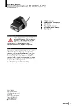
Operating Manual
Inductive Positioning System BIP AD0-B014-01-EP02
No. 872877 EN E16
3
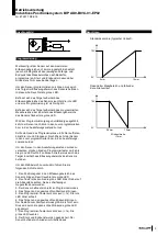
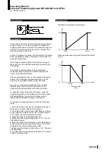
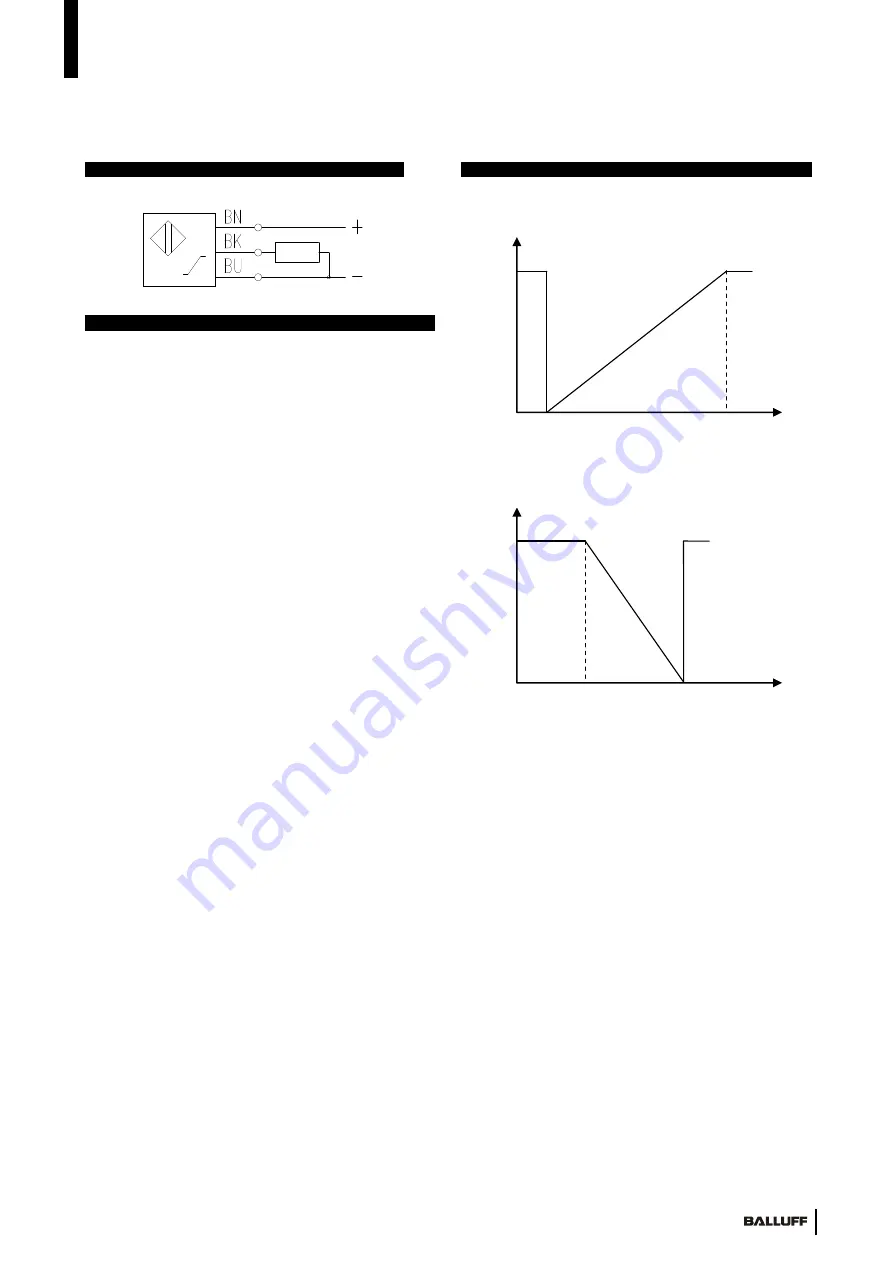
10V
0V
0mm
14mm
10V
0V
2,5mm
10mm
Minimum width
>7mm
Wiring diagram
Programming
The sensor is set at the factory to the maximum detection
range of 14mm. It is, however, possible to program the
respective start and end points of the measuring range as
needed. The start and end points must be at least 7mm
from one another in this case.
In order to program the sensor, the target must be located
within the detection range of the sensor. In this case, the
green LED illuminates.
If the target is located outside of the detection range of
the sensor, the red LED illuminates and programming is
not possible.
If the target is located outside of the programmed
measuring range but within the detection range of the
sensor, the green LED flickers.
If the programming process is not completed, the sensor
returns to the previously programmed state or, as the
case may be, the state of delivery after 2 minutes.
If an error occurs during programming, the red LED
flashes slowly. After 20s, the sensor returns to the
previously programmed state or the state of delivery.
To reset the sensor to the state of delivery, press the
programming button for approximately 8s until the green
LED stops flashing. In doing so, the target must be
located within the detection range of the sensor.
To change the measuring range, perform the following
steps.
1. Move the position encoder into the detection range of
the sensor. The green LED then illuminates.
2. Press the button until the green LED flashes. In doing
so, pay attention to the cover foil. Use no sharp objects.
3. The sensor is now in programming mode.
4. Move the target to the desired start point.
5. Briefly press the programming button (< 1s). The red
LED flashes rapidly.
6. Move the target to the desired end point. The distance
to the start point must be higher than 7mm. This is then
indicated by the rapidly flashing green LED.
7. Briefly press the programming button (< 1s). The green
LED illuminates.
8. The start and end points have been saved. The sensor
is again in working mode.
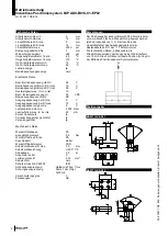
Characteristics
Standard characteristic (typical slope):
Reduced measuring range and falling characteristic
curve:


