background image

  Installing the Drive   3-3

MN762S

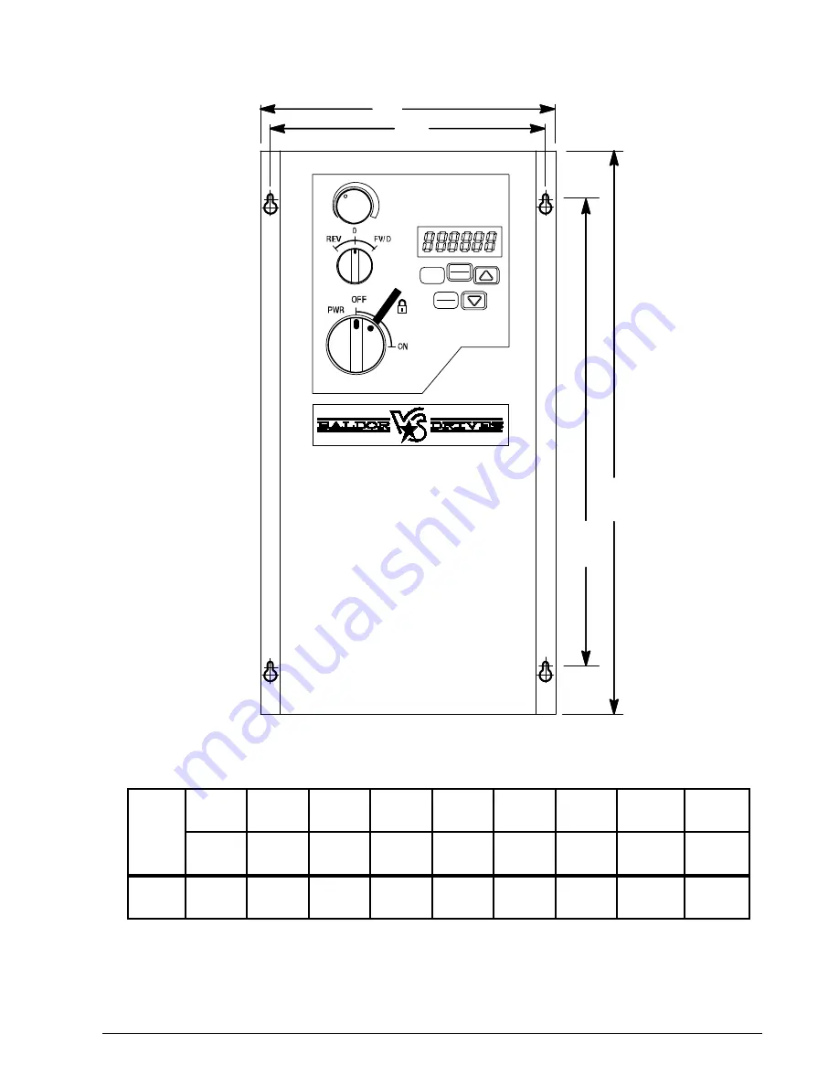
Figure 3-2  NEMA 12 / IP55 Mounting Hole Locations

A1

A

B 1

B

STOP

RESET

START

 PROG

 ENT


Table 3-2  NEMA 12 / IP55 Dimensions

Frame 

A

A1

A2

B

B1

Φ

Φ

(Depth)

Weight

in 

(mm)

in 

(mm)

in 

(mm)

in 

(mm)

in 

(mm)

in 

(mm)

in 

(mm)

in 

(mm)

lb

(kg)

B

12.20

(310)

12.20

(310)

1.30

(33)

6.46

(164)

6.02

(153)

0.17
(4.2)

0.33
(8.4)

7.09

(180)

9.92
(4.5)

Control Terminal Torque Settings of 4.5 lb-in (0.5 Nm)
Power Terminal Torque Settings of 9 lb-in (1 Nm)

Summary of Contents for VS1MXS series

Page 1: ...03 11 Installation Operating Manual MN762S VS1MXS AC Extreme Duty Microdrive...

Page 2: ...e the property of their respective owners Important Be sure to check www baldor com for the latest software firmware and drivers for your VS1MXS product Also you can download the latest version of thi...

Page 3: ...3 Protective Devices 4 2 4 4 Electrical Installation 4 2 4 4 1 Branch Circuit Protection 4 2 4 4 2 Single Phase Input Power Connections for 1 Phase Control 4 2 4 4 3 Three Phase Input Power Connection...

Page 4: ...ameter Adjustments 8 1 Chapter 9 Troubleshooting 9 1 Fault Codes 9 1 9 2 Periodic Inspection 9 1 Appendix A Technical Specifications A 1 Appendix B Parameter Tables B 1 Appendix C CE Guidelines C 1 CE...

Page 5: ...property PRECAUTIONS WARNING Do not touch any circuit board power device or electrical connection before you first ensure that power has been disconnected and there is no high voltage present from th...

Page 6: ...ult in extensive damage to the control The control is tested at the factory for high voltage leakage resistance as part of the Underwriters Laboratory requirements CAUTION Suitable for use on a circui...

Page 7: ...e 1 1 8 Turn power on Be sure there are no faults For switched version place the Power On Off switch in ON position 9 Set the following parameters for the values displayed on the motor nameplate P1 01...

Page 8: ...Analog Digital Output Analog Output 0 10VDC Optional Hardware not provided Only provided in Switched version Control Wiring Terminals Only on Switched versions Table 1 1 Control Terminal Descriptions...

Page 9: ...g label and the drive nameplate The model number includes the drive and any options Figure 2 1 Drive Identification VS1MXS 5 5 2 TD VS1 Family MXS Microdrive Voltage Code 5 500 600Vac 1PH Power Rating...

Page 10: ...s and Frame Sizes Table 2 1 Drive Ratings HP Model Number HP kW Current Amps Frame Watts Loss Input Output 500 600V 10 3 Phase Input VS1MXS51 1 0 75 2 2 1 7 B 50 VS1MXS52 2 1 5 4 1 3 1 B 90 VS1MXS53 3...

Page 11: ...n this manual 3 2 General Requirements for the Installation Site It is important to ensure that the drive s environment and operating conditions are satisfactory The area behind the drive must be kept...

Page 12: ...in NEMA 12 IP55 Type installations 3 3 2 Watts Loss Data Refer to Table 2 1 for watts loss data 3 3 3 Elevation Maximum elevation is 3300 ft 1000m above sea level without de rating De rate output powe...

Page 13: ...NT Table 3 2 NEMA 12 IP55 Dimensions Frame A A1 A2 B B1 I J C Depth Weight in mm in mm in mm in mm in mm in mm in mm in mm lb kg B 12 20 310 12 20 310 1 30 33 6 46 164 6 02 153 0 17 4 2 0 33 8 4 7 09...

Page 14: ...ic Gland Size B 1 11 28 2mm PG21 M25 866 22mm PG13 5 M20 Flexible Conduit Hole Sizes Frame Size Opening A and C Knock Out B Diameter UL Gland Size Metric Gland Size Diameter UL Gland Size Metric Gland...

Page 15: ...nded and must be purchased separately Note A line reactor is recommended and must be purchased separately Drive See recommended tightening torques in Table 4 1 Use UL Listed Fork terminals for ground...

Page 16: ...ustries Inc 4 4 Electrical Installation All interconnection wires between the drive AC power source motor host control and any operator interface stations should be in metal conduits or shielded cable...

Page 17: ...ake Resistor Value amps amps AWG mm2 Amps AWG mm2 Feet Meters Ohms 500 600V 10 3 Phase Input 1 0 75 2 2 3 15 1 1 7 15 1 164 50 47 2 1 5 4 1 6 15 1 3 1 15 1 328 100 47 3 2 2 5 4 6 15 1 4 1 15 1 328 100...

Page 18: ...r failure of the M contactor or wiring may damage the control If an M Contactor is installed the control must be disabled for at least 200msec before the M Contactor is opened or the control may be da...

Page 19: ...r ground The Control Wiring Terminals are prewired to allow front panel Potentiometer and FWD Off Rev switch operation Simply remove these terminal connections pins 1 to 7 and connect external devices...

Page 20: ...ks use the RS485 PIN connection see Appendix E for the communication protocols Figure 5 2 RJ11 Data Connection RS485 Modbus 0 Volts 24 Volts Optibus Optibus RS485 Modbus Table 5 2 Protocol Modbus RTU...

Page 21: ...erm 3 Digital Input 3 Term 4 Bipolar analog input Term 6 Speed Set point Open Open Open Preset Speed 1 Closed Open Open Preset Speed 2 Open Closed Open Preset Speed 3 Closed Closed Open Preset Speed 4...

Page 22: ...en Stop Open Bipolar analog speed ref Open Trip Bipolar analog input Closed Run Closed Preset Speed 1 Closed No Trip 12 Open Stop Open Preset Speed 1 Open Trip Bipolar analog input Closed Run Closed B...

Page 23: ...g input 2 speed ref 20 Open Stop Digital Output Open Bipolar analog speed ref Bipolar analog input Closed Run Drive Healthy 24V Closed Preset Speed 1 21 Open Stop Digital Output Open Forward Bipolar a...

Page 24: ...drive 10 Open Stop Closed Run Open Digital speed ref Closed Bipolar analog speed ref External trip input Bipolar analog input Open Trip Closed No Trip 11 Open Stop Closed Run Open Digital speed ref Cl...

Page 25: ...the use of the START STOP buttons In keypad mode the speed can be adjusted using the UP DOWN keys on the built in keypad or a remote mounted keypad in addition to push buttons connected to the digital...

Page 26: ...og input Open Trip Closed No Trip 17 Open Stop Closed Run Open PID control Closed Bipolar analog ref Analog input 2 Bipolar analog input 19 Open Stop Closed Run Open PID control Closed Analog input 2...

Page 27: ...ital Speed ref External trip input Bipolar analog input No Function Open Trip Closed No Trip 11 Open Stop Closed Run Open Master Speed ref Closed Preset Speed 1 External trip input Bipolar analog inpu...

Page 28: ...5 10 Control Wiring MN762S...

Page 29: ...pad mode Pressing for a period of time will increase the reference value rate of change In edit mode navigates between parameters and increments parameter values Decrease During operation decreases th...

Page 30: ...ntrol STOP Run in PID Control 3 11 In Speed Control P2 1 sets the Preset Speed In PID Control pot controls set point Run in Hand STOP Run in Auto 4 17 Hand Speed reference from Pot Auto Speed Referenc...

Page 31: ...s the key The and can be used to select the desired parameter etc The and can be used to select the desired parameter etc The and can be used to select the desired parameter Select the required parame...

Page 32: ...to return to speed display 12 To stop the motor either turn the potentiometer back to zero or disable the drive by opening the control switch terminals 1 2 13 If the enable disable switch is opened th...

Page 33: ...tune on the motor the first time it is enabled During the auto tune the display will show Auto t The test procedure may take several minutes to complete depending on the motor Once the auto tune is co...

Page 34: ...ocedure the motor shaft may turn It is not normally necessary to uncouple the load from the motor however the user should ensure that no risk arises from the possible movement of the motor shaft 6 10...

Page 35: ...he rated nameplate frequency of the motor P1 04 Motor rated speed 0 to 60 000 rpm Rpm 0 When non zero all speed related parameters are displayed in rpm Enter the motor rated nameplate speed if this is...

Page 36: ...oad as a generator 1 When the enable signal is removed from the drive the motor will coast freewheel to stop 2 When the drive enable signal is removed the drive will ramp to stop at the rate set in P1...

Page 37: ...order of occurrence the most recent first Press UP or DOWN to step through all four The most recent trip is displayed first UV trip is only stored once P1 14 Extended menu access Code 0 to 30000 0 Set...

Page 38: ...ncy P1 05 to P1 06 Hz Rpm 0 0 Centre point of skip frequency band set up in conjunction with P2 10 P2 10 Skip frequency band 0 to P1 06 Hz Rpm 0 0 Width of skip frequency band centered on frequency se...

Page 39: ...he motor speed matches the set point speed 3 Logic 1 when the motor runs above zero speed Options 4 to 6 the Digital output is enabled using the level set in P2 14h and P2 14L P2 14h Relay Output Cont...

Page 40: ...rmine if the motor is already rotating and will begin to control the motor from its current speed A short delay may be observed when starting motors which are not turning P2 19 Keypad Restart Mode 0 M...

Page 41: ...Enabled High Duty 3 Enabled No Protection 0 Enables the internal brake chopper Settings 1 and 2 provide software monitoring of the braking power consumption Setting 3 disables the protection and exter...

Page 42: ...addresses Only one drive can be programmed as a Master P2 29 Master Slave speed reference scaling factor 0 to 500 0 100 0 Scaling factor applied to any speed reference on the serial data link e g in...

Page 43: ...nd Master Slave mode only 1 Actual Speed Digital Speed x P2 29 2 Actual Speed Digital Speed x P2 29 bipolar analog reference 3 Actual Speed Digital Speed x P2 29 x bipolar analog reference P2 36 Analo...

Page 44: ...ds slowly P3 03 Differential time constant 0 00 to 1 0 Seconds 0 00 PID Differential Time Constant P3 04 PID operating mode 0 Direct 1 Inverse 0 Direct operation Motor speed increases with an increase...

Page 45: ...P3 07 P3 08 1 PID maximum output limited by the signal applied to the bipolar analog input 2 PID minimum output limited by the signal applied to the bipolar analog input 3 PID output is added to the s...

Page 46: ...he speed controller Too high a value may cause overshoot when accelerating to set point speed or instability of the motor output speed P4 04 Speed controller integral time 0 010 to 1 000 Seconds 0 050...

Page 47: ...perating in V f mode P4 01 2 sets a frequency point at which the voltage applied in P4 10 is applied to the motor Care must be taken to avoid overheating and damaging the motor when using this feature...

Page 48: ...PID error P0 09 PID P Term 0 to 100 Proportional component P0 10 PID I Term 0 to 100 Integral component P0 11 PID D Term 0 to 100 Differential component P0 12 PID Output 0 to 100 Output from PID contr...

Page 49: ...rive dependent Hz Rpm Vector mode estimated motor speed P0 26 kWh meter 0 to 999 9 kWh Cumulative energy consumption P0 27 MWh meter 0 to 60 000 MWh Cumulative energy consumption P0 28 Software ID IO...

Page 50: ...an auto tune the drive measures calculates these parameters to optimize the motor control performance The values can be adjusted by the user however this may have a negative effect on the motor behav...

Page 51: ...ion time constant typically 100 200 ms can be added before start up This function is only active when the drive is in vector control mode P5 08 Reserved P5 09 Over Voltage Current Limit 0 to 100 of mo...

Page 52: ...nto regeneration mode The output torque of the motor may reduce during regeneration if the value in this parameter is too small P5 11 Pulse Width Limitation 0 500 Time value 16 67ns Ms This parameter...

Page 53: ...Reset is enabled see P2 17 P6 04 User Relay Speed Hysteresis Band 0 0 25 0 0 3 This parameter defines a band around zero speed as a percentage of P1 03 When P2 11 or P2 13 2 or 3 output frequencies b...

Page 54: ...twork Master is being used to monitor the drive rather than control it a loss of communication will still cause the drive to trip P6 09 Speed Droop Control 0 0 25 0 of P1 03 Hz 0 This parameter only a...

Page 55: ...for the resistor should always be used to avoid this risk P6 11 Preset Speed Run Time On Enable 0 0 600 0 S 0 0 Defines a time period for which following an enable signal being applied to the drive th...

Page 56: ...rnal value P0 40 Current Phase V Offset Internal value P0 41 Current Phase V Ref Internal value P0 42 Brake Resistor Max on Time Time in milliseconds P0 43 Brake Resistor Duty Cycle Internal value P0...

Page 57: ...anation P0 57 Encoder Speed P1 06 to P1 06 Hz Rpm Displays the encoder speed P0 58 Speed Jump Zone Internal value P0 59 Modbus Write Command Data Value Register dependent P0 60 Motor Control Loop ID 0...

Page 58: ...7 24 Parameter Descriptions MN762S...

Page 59: ...Speed P1 04 Minimum Speed P1 05 Set P1 06 to the maximum speed and P1 05 to the minimum speed These limits can also be negative for reverse speeds If a non zero minimum speed is set in P1 05 the moto...

Page 60: ...8 2 Customizing Your Application MN762S...

Page 61: ...by P2 19 4 If the motor is stopped and the display shows STOP there is no fault the drive output is disabled and the drive is ready to run Read fault log as follows 1 Press and hold the Navigate to en...

Page 62: ...ccessfully completed for the connected motor Check the load mechanically for a jam or stalled condition or shock loads Increase the ramp up time in P1 10 If operating in Vector mode P4 01 0 or 1 reduc...

Page 63: ...ses Internal memory fault Parameters not saved defaults reloaded Try again If the problem re occurs refer to your Baldor District Office Autotune failed Measured motor stator resistance varies between...

Page 64: ...s been exceeded Refer to the Baldor District Office for further information 4 20mA Input Signal Loss The level of the 4 20mA signal applied to analog input 2 Terminal 4 has dropped below the minimum t...

Page 65: ...otor or control output shorted or grounded motor overload Stall Prevention Over voltage suppression over current suppression External Output LED trip condition indicators 4 assignable logic outputs 2...

Page 66: ...djustable 4 8 16 or 32kHz Speed Setting 0 10VDC 0 20mA digital keypad Accel Decel 0 3000 seconds Velocity Loop Bandwidth Adjustable to 180 Hz Control only Current Loop Bandwidth Adjustable to 1200 Hz...

Page 67: ...ead Only P0 11 RO PID D Term 0 to 100 Read Only P0 12 RO PID Output 0 to 100 Read Only P0 13 RO Output Torque 0 to 200 Read Only P0 14 RO Magnetizing Current Drive dependent Read Only P0 15 RO Rotor C...

Page 68: ...value Read Only P0 41 RO Current Phase V Ref Internal value Read Only P0 42 RO Brake Resistor Max on Time Time in milliseconds Read Only P0 43 RO Brake Resistor Duty Cycle Internal value Read Only P0...

Page 69: ...l Keypad PID Drive Control Mode Selection 0 Terminal control 1 Keypad control fwd only 2 Keypad control fwd and rev 3 PID Control 4 Modbus RTU Control 0 P1 08 RW Digital Input Function Select 0 to 22...

Page 70: ...t 0 0 to 200 0 100 0 P2 12L RW Digital Output Control Low Limit 0 0 to P2 12h 100 0 P2 13 RW User Relay Output Function Select 0 Drive enabled 1 Drive healthy 2 Motor at target speed 3 Motor Speed 0 4...

Page 71: ...2nd Deceleration Ramp Time 0 0 to 3000 0 0 0 P2 26 RW Modbus Communication Baud Rate t9 6 t19 2 t38 4 t57 6 t115 2 r9 6 r19 2 r38 4 r57 6 r115 2 t115 2 P2 27 RW Drive Communication Address 0 Disabled...

Page 72: ...02 RW Integral Time Constant 0 0 to 30 0 1 0 P3 03 RW Differential Time Constant 0 00 to 1 0 0 00 P3 04 RW PID Operating Mode 0 Direct 1 Inverse 0 P3 05 RW PID Set Point Reference Select 0 Digital 1...

Page 73: ...V f Characteristic Adjustment Voltage 0 to P1 01 0 P5 01 RW Motor Stator Resistance Rs Drive dependent P5 02 RW Motor Rotor Resistance Rr Drive dependent P5 03 RW Stator Inductance Ls Drive dependent...

Page 74: ...er Feedback Enable 0 Disabled 1 Enabled 0 P6 06 RW Encoder PPR 0 10000 0 P6 07 RW Encoder Speed Error Limit 0 0 50 0 5 0 P6 08 RW Modbus Communication Loss Timer 0 disabled 1 60 2 P6 09 RW Speed Droop...

Page 75: ...sponsibility of the system integrator to ensure that the entire system complies with all relative directives at the time of installing into service Motors and controls are used as components of a syst...

Page 76: ...ommended AC supply filter and having met all cable requirements Note Radiated magnetic and electric fields inside the cubicle will be high and components installed inside must be sufficiently immune T...

Page 77: ...e power supply here BPS For the connection to and from the main lter screened cables should be used The cable screens should be connected to screen clamps on both sides Exception Analog Command Signal...

Page 78: ...nnected to the screen rails or clamps The screen rails or clamps should be conductive clamps fastened to the cabinet 2 D The cable to the regeneration resistor must be shielded The shield must be conn...

Page 79: ...iption VS1STS J11SP RJ11 Cable Splitter VS1STS USBPC RS485 to USB Cable VS1STS CBL0P3 0 3m RJ11 Cable VS1STS CBL1 1m RJ11 Cable VS1STS CBL3 3m RJ11 Cable Option Cards for VS1MXS Provides additional re...

Page 80: ...D 2 Options and Kits MN762S...

Page 81: ...stop the drive over the network P2 26 Baud Rate Select the baud rate utilized by the master device on the network All devices on the network must utilize the same baud rate P2 27 Drive Address Set to...

Page 82: ...Check CRC Data Format 1 start bit 8 data bits 1 stop bits no parity Physical Signal RS 485 2 wire User Interface RJ11 Protocol Modbus RTU E 7 Communications Protocol MODBUS RTU The VS1MXS supports Ma...

Page 83: ...it Word Bit 0 Low Stop High Run Enable Bit 1 Low No Function High Fault Reset Bit 2 Low Decel Ramp 1 P1 11 High Decel Ramp 2 2 R W 03 06 Modbus Speed reference setpoint 0 20000 Setpoint frequency x10...

Page 84: ...Bit 1 Input 1 22 P0 02 R 03 2nd analog input value 0 1000 Analog input of full scale x10 e g 1000 100 40 P0 20 R 03 DC bus voltage 0 1000 Analog input of full scale x10 e g 1000 100 41 P0 21 R 03 Dri...

Page 85: ......

Page 86: ......

Page 87: ...VA SAN SALVADOR EL SALVADOR PHONE 503 2288 1519 FAX 503 2288 1518 CHILE LUIS THAYER OJEDA 166 OF 402 PROVIDENCIA SANTIAGO CHILE PHONE 56 2 816 9900 CHINA 160 SONG SHENG ROAD SONGJIANG INDUSTRY ZONE SH...

Page 88: ...ted in USA 03 11 762S 0311 P O Box 2400 Fort Smith AR 72902 2400 U S A Ph 1 479 646 4711 Fax 1 479 648 5792 International Fax 1 479 648 5895 Baldor Dodge 6040 Ponders Court Greenville SC 29615 4617 U...

Reviews: