3
MN914
Overview
Belt grinding or finishing has many advantages over the use of conventional grinding wheels.
It is possible to remove material up to 5 times faster than the equivalent grade of grinding
wheel with far less heat. The electrostatic process used in the manufacture of an abrasive
belt ensures that the sharp side of each piece of grit is facing outwards on the belt thus giving
cleaner, smoother and faster cutting. The flexing of the belt has a self cleaning action and
also it does not overheat, making it more suitable to any application where heat could
damage the work, for example, grinding leather, plastics, tool sharpening etc.
Select the correct belt for the application, see Table 2.
Disc grinding is a very useful and versatile part of the attachment. It is very useful for dressing
small castings and components, patterns, models, etc., often eliminating costly machining.
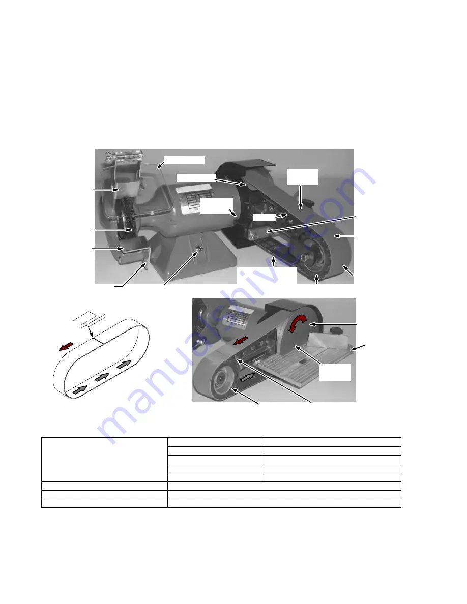
Figure 1
On-Of f Switch
Wire Brush
Tool Rest Support
Eyeshield
Catch
Tool Rest
Optional
Table
Abrasive Disc
Front of Grinder
Rotation
Direction
Belt
Lap
Spark Arrestor
Platen
Abrasive
Belt
Idler Pulley
Tracking
Lever
Contact Wheel
Grinding
Platen
Grinding
Free Strapping
Grinding
Disc
Grinding
Drive Pulley
Idler Pulley
Shown with optional
table installed.
Table Support
Bracket
Belt/Disc Specifications
Belt size 36” x 2” (915 x 50); Disc size 7” (178).
Table 2 Belt Applications
All Metals
Coarse Finish
Use 40 to 80 Grit Aluminum Oxide Belts.
Medium To Fine
Use 100 to 180 Grit
Very Fine
Use 240 to 400 Grit
Microfinishing
Use 3M Trizact 600 to 2000 Grit
Heavy Grinding Or Thin Sections
Use Zirconia Belts 40,60,80 Grits
Aluminum
Always use belt grease to prevent clogging
Wood
Use Aluminum Oxide Resin Bond open or Close Cote 40,60,80,100,120 Grits
Plastics, Glass Ceramic, General Lapidary
Use Silicon Carbide Resin Bond Close Cote 40 to 600 Grit


