background image

Page 7

56016-01_97_A

G

R

B

W

W

W

FUSE 20A 250V

FUSE 3A 250V

K8

K5

J46

F1

J29

J47

J20

J1A

J10

J1

W2

W3

Circ.Pump

12V 

Light

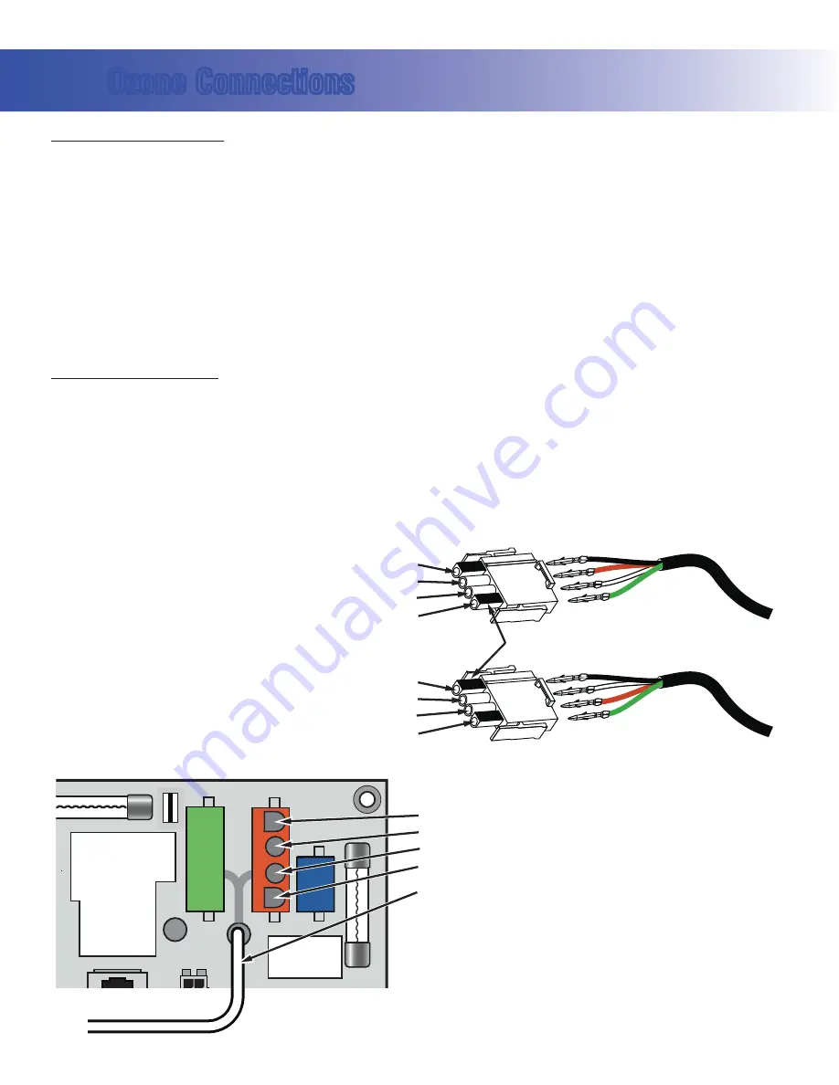
Use this slot for the leftover Red conductor

Line - Black conductor

Balboa Ozone connector configuration for 120V 60Hz 

Ground (Green) conductor

Flat sides of sockets as shown

Common - Install the White conductor here for 120V ozone

Use this slot for the leftover White conductor

Line - Black conductor

Balboa Ozone connector configuration for 240V 60Hz 

Ground (Green) conductor

Common - Install the Red conductor here for 240V ozone

B

G

B

G

Use this slot for the leftover conductor

Line - Black conductor

Ground (Green) conductor

Common - Red for 240V or White for 120V ozone (See W2 wire)

W2 wire determines voltage

Ozone Connections

Ozone Connector Voltage:

 The VS500Z circuit board is factory configured to deliver a preset voltage (120V or 

240V) to the on-board ozone connector (J29). See the ratings table on the wiring diagram attached to the cover 
of the enclosure for the configured voltage.  For 240V output W2 connects to Red AC and for 120V output W2 
connects to White AC.

The voltage to the ozone connector can be changed in the field if required. W2 just needs to be set for the 
required voltage.

WARNING: Changing the voltage of the ozone connector also effects the voltage supplied to the circ 
pump connector (J47). Any equipment controlled by that connector may be damaged if the wrong voltage 
is selected.

Balboa Ozone Generator:

 If the board is set up to operate a 120V ozone generator, the connector on the ozone 

generator is likely to be configured correctly, but should be compared to the illustration below.

If a 240V ozone generator is required, be sure the red wire in the ozone cord is positioned in the connector next 
to the green ground wire as described below.

Note: A special tool is required to remove the pins from the connector body once they are snapped in place. 
Check with your Balboa Account Manager for information on purchasing a pin-removal tool.

Summary of Contents for VS520DZ

Page 1: ...f 04 08 2008 Template used 40600_P pdf 01 07 2008 Balboa Instruments System PN 56016 01 System Model VSP VS520DZ YCAH Software Version 43 EPN 2765 Base PCBA PN 55152 01 PCB VS500Z PN 22972 Rev D or E Base Panels VL801D Serial Deluxe PN 54108 VL802D PN 54528 ...

Page 2: ...By Changes Made 56016 1954 09 20 2006 Balboa New system 56016 2528 09 25 2007 Balboa Update to 48A serviceYCAH 56016 2528 10 05 2007 Balboa Software update to v41 A5 ON 56016 2528 10 18 2007 Balboa Software revert to v39 56016 01 2765 04 08 2008 Balboa Software update to v43 ...

Page 3: ... NEUTRAL GROUND System Outputs BALBOA INSTRUMENTS INC VS500Z P N 22972 REV D MADE IN U S A COPYRIGHT 2005 J7 J8 J44 J60 J22 U4 FUSE K8 K5 J1A J10 J13 J2A EXT RLY AUX F SEN A SEN B VAC J1 J2 W2 W3 J12 1 2 3 2 SPD EXT RLY J18 Basic System Features and Functions Setup 1 As Manufactured s 6 0UMP 3PEED s 6 0UMP 3PEED s 6 LOWER s 6 ZONE s 6 3PA IGHT s 6 6 Stereo s 6 K7 EATER Optional Devices s 6 IRC 0UM...

Page 4: ... that is a VS511SZ at version 38 s Displayed next is indicating the system is configured for a heater between 3 and 6 kW or indicating the system is configured for a heater effectively between 1 and 3 kW should appear for all VS models running at 240VAC should appear for all VS models running at 120VAC as well as all GS models A heater which is rated at 4 kW at 240VAC will function as a 1 kW heate...

Page 5: ...2 Spd P1 PCBA Rev D E only Black jumper required Do not remove Wiring Configuration and DIP Settings Setup 1 As Manufactured s 6 0UMP 3PEED s 6 0UMP 3PEED s 6 LOWER s 6 ZONE s 6 3PA IGHT s 6 6 Stereo s 6 K7 EATER s 6 6 AIN 0ANEL s 6 IRC 0UMP OPTIONAL A1 Test Mode OFF A2 See Table 1 A3 N A A7 J17 26 Disabled A10 See Table 1 A9 Non Circ Mode A5 2 speed P1 Panel Button Assignments 1 Time 2 Mode Prog ...

Page 6: ...g DIP switches incorrectly may cause abnormal system behavior and or damage to system components sRefer to Switchbank illustration on Wiring Configuration page for correct settings for this system sContact Balboa if you require additional configuration pages added to this tech sheet Panel Button Positions Aux Panel Information Panel Button Assignments 1 Time 2 Mode Prog 3 Temp Up 4 Temp Down 5 Lig...

Page 7: ... J29 See the ratings table on the wiring diagram attached to the cover of the enclosure for the configured voltage For 240V output W2 connects to Red AC and for 120V output W2 connects to White AC The voltage to the ozone connector can be changed in the field if required W2 just needs to be set for the required voltage WARNING Changing the voltage of the ozone connector also effects the voltage su...

Page 8: ...N 54108 with Overlay PN 10763 s Connects to Main Board terminal J1 only S ETUP 1 Blower Time Warm Mode Prog Cool Jets 1 Light Jets 2 VL802D PN 54528 with Overlay PN 11789 s Connects to Main Board terminal J1 only Panels with back lighting bulbs installed should never be plugged into J2 Use J1 only If the backlight bulbs are removed then both J1 and J2 may be used ...

Reviews: