GATEWAY ULTRA
Module
(side view)
LED Light
Power
Cord
Ethernet
Cable
Home Router
GATEWAY ULTRA
Module
Home
Router
HOME
GATEWAY ULTRA
Module
(side view)
GATEWAY ULTRA
Module
(side view)
LED Light
Power
Cord
RS485 Power/Data Cord
BP Control
System
Ethernet
Cable
Home Router
LED Light
GATEWAY ULTRA
Module
Home
Router
GATEWAY ULTRA
Module
BP Control
System
GATEWAY ULTRA
Module
BP Control
System
HOME
SPA
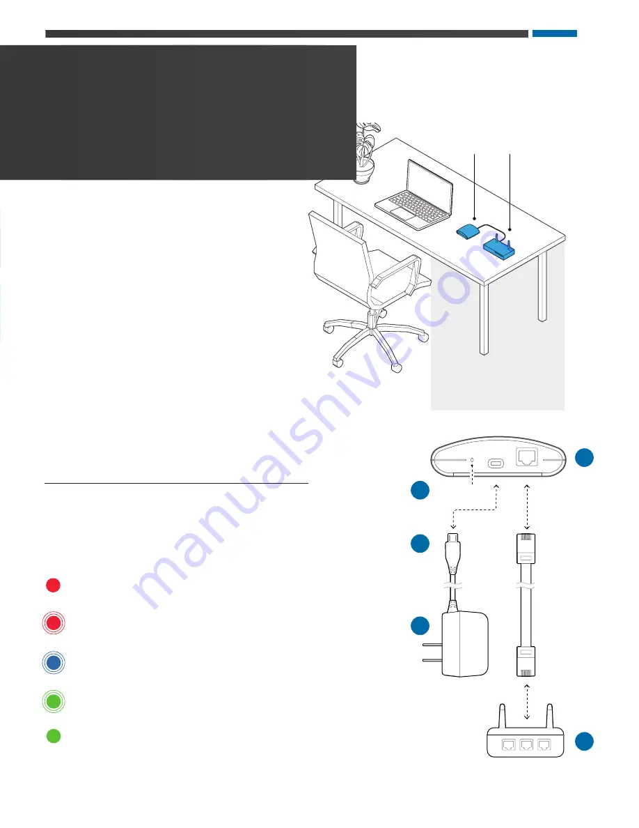
Connect GATEWAY ULTRA
hardware in your home
Step 1
Plug the supplied ethernet cable into the home router (A).
Step 2
Plug the other end of the ethernet cable into the
GATEWAY ULTRA module (B).
Step 3
Plug the supplied power cord into the GATEWAY ULTRA module (C).
Step 4
Plug the other end of the supplied power cord into wall power (D).
LED Light Chart (E)
This chart applies to the home and spa GATEWAY ULTRA modules.
A
B
C
D
E
Red - Solid: The GATEWAY ULTRA and the spa
are not connected.
Red - Blinking: Home and spa GATEWAY ULTRA modules are
connected, but no connection to the spa controller.
Blue - Blinking: Remote software update is underway. Do not
unplug power.
Green - Blinking: CMS™ GATEWAY ULTRA spa and home
modules RF is connected, but no connection to internet.
Green - Solid: Spa successfully connected to internet. No errors.
42317_Rev. C
7
ControlMySpa™ Retrofit User Guide
Summary of Contents for ControlMySpa GATEWAY ULTRA
Page 5: ...ControlMySpa GATEWAY ULTRA INSTALLATION GUIDE 42317_Rev C 5 ControlMySpa Retrofit User Guide...
Page 15: ...ControlMySpa ACCOUNT SETUP AND SPA CONNECTION 42317_Rev C 15 ControlMySpa Retrofit User Guide...
Page 26: ...ControlMySpa Website Overview SPA OWNER 26 ControlMySpa Retrofit User Guide 42317_Rev C...
Page 28: ...ControlMySpa SPA VIEW PAGE Spa Owner Overview 28 ControlMySpa Retrofit User Guide 42317_Rev C...


