33
1
.
If the System Control is not installed in a building and
is otherwise not influenced by direct sunlight, the
temperature sensor can be mounted to the bottom of
the enclosure.
2
.
In the low-voltage raceway, remove the knockout
located next to the low-voltage cable slot, then install
the Liquid-Tite connector.
3
.
Loosen, but do not remove the sealing nut from the
connector. Insert the Air Temperature Sensor into the
Liquid-Tite connector and tighten the sealing nut.
4.
Plug the Air Temperature Sensor connector into the
2-pin header labeled AIR.
5.
Neatly bundle the excess sensor cable into
the low-voltage raceway and secure with the
tie wrap supplied.
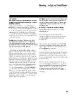
Fig. 24 System Control Center Location Mount Option
1
.
If an optional electronic filter pressure sensor is purchased, screw the sensor into the “tee” near the pressure
dial indicator.
2
.
Run the sensor cable back to the low-voltage compartment of the System Control Center and plug the connector into the
3-pin terminal block TB2 labeled PRESSURE using the following table:
CONNECTION
LABEL
WIRE
COLOR
+V
RED
IN
WHITE
GND
BLACK
1
.
If an optional solar heating sensor is purchased, install the solar sensor near the solar panels.
2
.
Run the sensor cable back to the low-voltage compartment of the System Control Center and plug the connector into the
2-pin header J10 labeled SOLAR.
WARNING: DO NOT USE 10K OHM SENSORS OR OTHER MANUFACTURER’S SENSORS WITH THIS CONTROL.
INCORRECT TEMPERATURE READINGS WILL RESULT.
AIR TEMPERATURE SENSOR INSTALLATION (IN THE SYTEM ENCLOSURE)
TO INSTALL AN OPTIONAL SOLAR SENSOR (NOT PROVIDED)
TO INSTALL AN OPTIONAL FILTER PRESSURE SENSOR (NOT PROVIDED)


