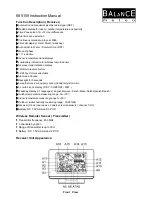
Part A-LCD
A1: Max-Min memory
A2: Indoor temperature and humidity
A3: Channel
A4: Outdoor temperature and humidity
A5: RF icon
A6: Transmitter Low battery power display
A7: Alarm icon
A8: Dual time ( DCF )
A9: Calendar A10: Radio controlled time
A11: Radio controlled icon
A12: 12HR air pressure history
A13 Moon of phase
A14: Barometric air pressure
A15: comfort icons
A16: Air pressure trend indication
A17: Weather forecast icon
Part B-Buttons
B1: “ DOWN –WAVE ” button
B2: “- ( UP / MEM )” button
B3: “ CHANNEL “ button
B4: “ SNOOZE / LIGHT ” button
B5: “ALM-SET” button
B6: “ SET ” button
B7: “ RESET ” button
Part C-Structure
C1: Insert DC adapter jack C2: Stand
C3: Battery door
C4: Wall mount hole
Wireless Remote Sensor Appearance:
Back View
Front
View
Back View
Back View
Top View
Front View
Summary of Contents for 695159
Page 7: ......


