background image

3. ELECTRICAL CONNECTIONS

1

Installation must be performed by a licensed electrician.

2

A separate electrical connection to the mains must be provided for each oven.

3

An all pole disconnect must be provided by the installer.

4

Connection to the electrical service must be grounded in accordance with local codes. In the
absence of local codes refer to the National Electric Code, ANSI/NFPA 70 or the Canadian Electric
Code, CSAC22.2 as applicable.

5

Only bare copper conductors with a minimum insulation temperature rating of 90ºC to be used.

6

The installer must supply a properly sized strain relief bushing for the mains connection that meets
all codes.

7

The oven shall be installed using flexible conduit.

8

The restraint cord must be securely attached to the rear of the oven and to the building structure to
prevent transmitting unnecessary stress to the flexible conduit.

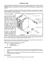
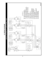
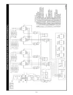
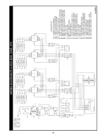
A wiring diagram is affixed to the inner side cover of the oven and included in the rear of this booklet.
The input connection is accessed be removing the right side cover. Field connections are located at the
lower rear corner of the control compartment.

!

!

WARNING:

Risk of electrical shock. Appliance must be secured to building structure.

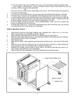
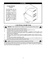
Double Stacked

Ovens

Your EP-2-2828 may be
stacked two ovens on top of
one another.

In order to

insure the ovens to not slide
or separate, there is a
stacking bracket kit required
for installation at the rear of
the ovens.

Two brackets

are installed, one at each
end of the oven securing the
upper oven to the bottom
oven. Refer to the adjacent
illustration.

STACKING

#10 SHEET METAL

SCREW (8)

C5057X BRACKET (2)

6

!

!

Caution:

Disconnect all ovens from electrical supply before servicing.

Summary of Contents for EP-2-2828 Single

Page 1: ...ENCE OVEN MUST BE KEPT CLEAR OF COMBUSTIBLES AT ALL TIMES Form U4186A 5 05 1 Initial heating of this oven may generate smoke or fumes and must be done in a well ventilated area Overexposure to smoke o...

Page 2: ...iagrams 13 11 Warranty 16 IMPORTANT FOR FUTURE REFERENCE Please complete this information and retain this manual for the life of the equipment For Warranty Service and or Parts this information is req...

Page 3: ...mains Ovens are shipped individually 3 28 711mm 28 711mm 208 1 44 9 5 44 208 3 25 9 5 30 31 32 230 1 39 9 5 39 240 1 38 9 5 38 240 3 22 9 5 22 23 23 400 3 13 9 5 13 12 13 Volts Amperes kW Nominal Ampe...

Page 4: ...led with adequate clearance to combustible and non combustible walls If legs are not used the oven must be sealed to the countertop with an NSF approved sealant M i n i m u m o p e r a t i n g clearan...

Page 5: ...make sure the two casters with brakes are installed at the front of the oven 6 Carefully stand up the oven Insure the two legs casters that touch the floor first when you raise the oven are blocked a...

Page 6: ...attached to the rear of the oven and to the building structure to prevent transmitting unnecessary stress to the flexible conduit A wiring diagram is affixed to the inner side cover of the oven and i...

Page 7: ...ted from 200 F Each cavity has top and bottom infinite control switches Turning the dial of the infinite control to 0 will turn off the heat for that portion of the oven cavity The proportion of heat...

Page 8: ...timer goes off Product should be removed from the oven as soon as possible to avoid overcooking 13 When baking weigh or measure the product in each pan to assure even cooking 14 Only bread and pizza m...

Page 9: ...rumble and easily brush out afterwards Do not use oven cleaners caustic solutions or mechanical means that may damage the interior of your oven Exterior Cleaning Never spray steam or water directly on...

Page 10: ...Element 230V 750W Lower Element 208V 750W Lower Element 240V 750W Front Element 230V 750W Front Element 208V 750W Front Element 240V 750W Snap Bushing Terminal Block Ground Lug Wire Clamp Stone Hearth...

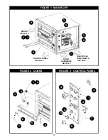
Page 11: ...URE 1 MAIN BODY ELECTRICAL COMPONENTS SEE FIG 5 DOORS SEE FIG 2 CONTROL PANEL SEE FIG 3 DOOR HARDWARE SEE FIG 4 9 1 2 3 4 5 6 7 8 1 2 4 3 5 6 7 FIGURE 2 DOORS FIGURE 3 CONTROL PANEL 11 1 2 3 4 5 6 8 8...

Page 12: ...04 Apr 04 10 9 1 2 3 3 4 5 5 6 6 7 8 FIGURE 4 DOOR HARDWARE 12 FIGURE 5 ELECTRIC COMPONENTS 1 2 3 4 5 6 7 8 9 FIGURE 5 ELECTRIC COMPONENTS ITEM FROM TO USAGE DATES PART NO DESCRIPTION QTY C5025X P100...

Page 13: ...13...

Page 14: ...14...

Page 15: ...15...

Page 16: ...he product The serial number rating plateaffixed to the equipment has not beendefaced or removed WHO IS COVERED This warranty is extended to the original purchaser and applies only to equipment purcha...

Reviews: