background image

XX & CH CHARBROILER OPERATION MANUAL

7

OPERATING INSTRUCTIONS

Average Production Guide:
Estimated Hourly Production

MODEL NUMBER

BROILING AREA

3 OZ. BURGERS

12 OZ. STEAKS

CH-4   XX-4

21” x 24”

600

120

CH-6   XX-6

31 1/2” x 24”

900

180

CH-8   XX-8

42” x 24”

1200

240

CH-10   XX-10

52 1/2” x 24”

1500

300

CH-12   XX-12

63” x 24”

1800

360

CH-14

73 1/2” x 24”

2100

420

CH-16

84” x 24”

2400

480

The table above gives estimated hourly production as a guide only. Actual production may vary depending on required 
doneness, thickness and weight of product.

TROUBLESHOOTING GUIDE

CAUTION: Take extreme care to assure that, if a valve 
is opened, a flame is present. If a valve is left open 
without a flame, turn the valve off and wait at least five 
minutes before attempting to (re)light. Service should be 
performed only by a qualified gas technician.

Burner Flame Adjustment:

(a)  The burner flame should be as blue as possible. 

However, there will be traces of orange and/or 
yellow from particles in the air burning in the 
flame. Slight yellow tips at the flame ends are 
acceptable.

(b)  If the flame appears yellow, loosen the air-mixer 

cap hold down screw “A” (see figs. 2 and 3). 
Rotate the air mixer cap counter-clockwise to allow 
more air into the burner, until the flame turns blue. 
Tighten the screw.

Pilot Flame Adjustment:

The pilot flame can be adjusted by turning the 
appropriate adjusting screw using a screwdriver or a 
3/16 wrench (see fig. 2), counter-clockwise to increase, 
clockwise to decrease and close. The pliot flame should 
be about 1/2 inch long.

Lack Of Heat:

Check to see if the pilot flames are on. If they are on but 
the burners do not light, or the burner flames look weak, 
then there is a possibility of a gas pressure loss to the 
broiler.

(a)  Check that the unit’s main valve is fully open. 

Normally in the open position, the valve handle 
will be parallel to the piping. The valve should 
be located somewhere on the gas line feeding 
the charbroiler. If the handle is NOT parallel to 
the piping, the unit is not getting the gas supply 
required to operate properly. Turn the valve handle 
parallel to the gas supply line.

(b)  If there is a problem with the gas supply, it may be 

checked fairly easily. Turn off half of the burners 
or turn off all other gas appliances and see if the 
broiler flames increase. If there is an increase in 
the flame height then there is a problem with the 
gas supply. A problem with the gas supply requires 
immediate attention. IMMEDIATELY close all the 
burner valves (turn to the off position), including 
the charbroiler’s main valve. Contact a qualified 
service agency or the public gas company.

Summary of Contents for Dante CH-14

Page 1: ...BUILT BY CRAFTSMEN TESTED BY TIME SERIES XX CH OPERATION MANUAL DANTE SERIES GAS CHARBROILERS ...

Page 2: ... installation adjustment alteration service or maintenance can cause property damage injury or death Read the installation operating and maintenance instructions thoroughly before installing or servicing this equipment WARNING Instructions must be posted in a prominent location All safety precautions must be taken in the event the user smells gas Safety information can be obtained from your local ...

Page 3: ...TION GUIDE 7 TROUBLESHOOTING GUIDE 7 BURNER FLAME ADJUSTMENT 7 PILOT FLAME ADJUSTMENT 7 LACK OF HEAT 7 ONE BURNER FAILS TO LIGHT 8 TROUBLESHOOTING CHART 8 VALVE ASSEMBLY VIEWS 9 PARTS LISTS EXPLODED VIEWS 10 MODELS XX 4 6 8 10 12 PARTS LISTS EXPLODED VIEWS 10 MODELS CH 6 8 10 12 14 PARTS LIST EXPLODED VIEW 13 WARRANTY 15 SAFETY PRECAUTIONS This symbol warns of imminent hazard which will result in ...

Page 4: ...d in non combustible locations only including above the grate level Minimum Clearance From Non Combustible Construction Series Right Left Back XX 0 0 0 CH 0 0 0 For units using propane gas supply lines less than 1 2 inside diameter should not be used even for a small unit On the XX and CH series the gas connection is located on the right rear of the unit Be sure to cap whichever side is not connec...

Page 5: ...ler has a standing pilot burner that must be lit before the burners can be lit To light the pilot burners a Turn all broiler valves to the off position b Remove each top grate and radiant c Open main gas SHUT OFF valve supplied by customer d Allow air to bleed from the gas line through the pilot burners e Light the pilot burners using a lit taper f Turn the burner control valves ON to light the bu...

Page 6: ...ce that complies with the latest edition of the Standard for Quick Disconnect Devices for use with gas fuel ANSI Z21 41 in USA CAN 1 6 7 in Canada and adequate means must be provided to limit the movement of the appliance without depending upon the connector and any quick disconnect device or its associated piping to limit the appliance movement c The restraint should be attached to the legs on wh...

Page 7: ...before broiling will compensate for the shrinkage Broil a hamburger as you would broil a steak 1 Be sure that the charbroiler has had adequate pre heating time so that the hamburger does not stick to the broiler grate 2 Place the hamburger on the grate and allow it to cook until release is attained 3 Once the hamburger releases from the grate turn it over and allow it to cook for 1 minute then tur...

Page 8: ...ce flare up trimming excess fat for a longer broil time without burning e Keep the unit clean Food caught between the grates will not allow hot air to rise around the product This will result in uneven heating and increase cook time Maintenance a Service Shut off the main gas supply before attempting any maintenance on the unit If required contact your Dealer the Factory or a local Service Company...

Page 9: ... air into the burner until the flame turns blue Tighten the screw Pilot Flame Adjustment The pilot flame can be adjusted by turning the appropriate adjusting screw using a screwdriver or a 3 16 wrench see fig 2 counter clockwise to increase clockwise to decrease and close The pliot flame should be about 1 2 inch long Lack Of Heat Check to see if the pilot flames are on If they are on but the burne...

Page 10: ...ough to clear the burner orifice fig 3 or 4 Using a thin wire or pin check to see that the orifice is clear taking care not to enlarge the hole Replace the burner radiant and grate and attempt to light it again If the burner will not light the burner valve could be defective Contact your dealer the factory or a local service company For additional information contact Bakers Pride Oven Co Inc 914 5...

Page 11: ...XX CH CHARBROILER OPERATION MANUAL 9 VALVE ASSEMBLY VIEWS Valve Assembly Views Figure 2 Air Mixer Cap And Pilot Burners Figure 3 Side View CH Series A Cap Hold Down Screw Figure 3 Side View XX Series ...

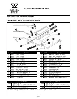
Page 12: ...er Only C I 24 w Mixer Cap XX O S 18 R3022X Air Mixer Cap w Screw C I Burner only 19 H1008X Grease Guard Only C I Burner 20 T1007A Radiant Cast Iron 23 Optional Shown 21 T1155T Radiant S S 23 Standard 22 M1009X Pressure Regulator 3 4 10 WC 23 M1008X Pressure Regulator 3 4 5 WC 24 R3043X Orifice Hood 47 Nat XX 25 R3044X Orifice Hood 55 LP XX 26 R3023X Orifice Hood Blank 27 T5041T Grate Lifter Cast ...

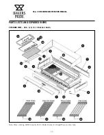
Page 13: ...XX CH CHARBROILER OPERATION MANUAL 11 PARTS LISTS AND EXPLODED VIEWS EXPLODED VIEW XX 4 6 8 10 12 Exterior Grates Note When ordering ALWAYS specify Part Model Serial Voltage Phase and Gas Type ...

Page 14: ...EXPLODED VIEWS Item Part No Description 11 G1081X Splash Guard S S XX 4 Optional G1082X Splash Guard S S XX 6 Optional G1083X Splash Guard S S XX 8 Optional G1084X Splash Guard S S XX 10 Optional G1237U Splash Guard S S XX 12 Optional 12 T3033T Grease Pan XX 4 12 20 3 8 1 used T3034T Grease Pan XX 6 XX 10 30 7 8 1 used T3035T Grease Pan XX 8 19 5 8 2 used or XX 12 1 used T3036T Grease Pan XX 10 19...

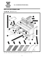
Page 15: ...XX CH CHARBROILER OPERATION MANUAL 13 PARTS LISTS AND EXPLODED VIEWS EXPLODED VIEW CH 6 8 10 12 14 Note When ordering ALWAYS specify Part Model Serial Voltage Phase and Gas Type ...

Page 16: ... 3 CH 16 44 T3124X Grease Pan set 3 CH 18 45 T3125X Grease Pan set 4 CH 20 46 T3126X Grease Pan set 4 CH 22 47 T3078V S S Heat Shield w Handle CH 4 48 T3079V S S Heat Shield w Handle CH 6 49 T3080V S S Heat Shield w Handle CH 8 50 T3081X S S Heat Shield w Handle set 2 CH 10 51 T3082X S S Heat Shield w Handle set 2 CH 12 52 T3083X S S Heat Shield w Handle set 3 CH 14 53 T3084X S S Heat Shield w Han...

Page 17: ...iants Stones and Valves are covered for a period of SIX MONTHS All Ceramic Baking Decks are covered for a period of THREE MONTHS The installation of these replacement decks is the responsibility of the purchaser The extended Cyclone door warranty years 3 through 5 is a parts only warranty and does not include labor travel mileage or any other charges EXCLUSIONS Negligence or acts of God Failures c...

Page 18: ...t offering a wealth of refrigeration and cooking expertise Products include walk in coolers and freezers hot and cold display cabinets cases and storage systems commercial ovens rotisseries and cooking equipment and rotary vane pumps Ask your sales representative about how the power of all Standex brands can work for you www standex com segments food service Food Service Equipment Group ...

Reviews: