background image

PV4-118310 

PAGE 20 

FIGURE 22 | 

INSTALLING THE PULLEY 

SPACER AND THE MAIN DRIVE GEAR SEAL 

FIGURE 23 | 

MAIN DRIVE GEAR SEAL 

INSTALLED FLUSH WITH CASE 

INSTALLING THE MAIN DRIVE GEAR 


8.  Put some transmission fluid on the 

outer diameter and O-ring of the pulley 
spacer. Install it onto the main drive 
gear with the O-ring facing inward 
(toward the bearing); see figure 22. 
 

9.  Put some transmission fluid on the lip 

of the main drive gear seal and install 
it. Make sure the seal is flush with the 
transmission case all the way around 
the bearing boss; see figure 23.


Summary of Contents for GRUDGEBOX

Page 1: ...PV4 118310...

Page 2: ...k component removal 13 Transmission case preparation 14 Tapered bearing adapter preparation 15 Heating the transmission case 16 Tapered bearing adapter installation 17 Countershaft bearing and main dr...

Page 3: ...eassembly of the motorcycle You will notice that the transmission will shift smoother and operate quieter after about 2500 miles Like any machine scheduled oil changes are key to years of trouble free...

Page 4: ...ckness Generally speaking torque capacity of a transmission is the product of the gearset center distance gear engagement width and circumferential tooth thickness at the pitch line 4 Tapered roller m...

Page 5: ...oor like a 3D puzzle to yield the Sleeper door which fathered the name GrudgeBox figure 1 Externally the GrudgeBox with the Sleeper door gives no indication that a drag racing transmission lives under...

Page 6: ...07 o H D equivalent 47910 Countershaft bearing service tool o BAKER TOOLE 07 Primary drive locking tool o H D 48219 Touring models o H D 47977 Softail Dyna Primary fluid 40 oz Touring models or 46 oz...

Page 7: ...O ring 33334 GB OR568M52 Main drive gear seal 12074 67 85mm beveled internal retaining ring VHO 334STPA 102 bearing spacer 11615 GB white shown 104 bearing spacer 11620 GB green pre installed 106 bear...

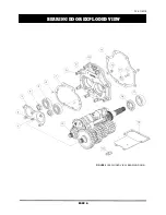
Page 8: ...PV4 118310 PAGE 6 BEARING DOOR EXPLODED VIEW FIGURE 3 EXPLODED VIEW BEARING DOOR...

Page 9: ...s 341 x 560 x 058 10 108 GB 1 Bearing door GrudgeBox chrome 118 GB 1 Bearing door GrudgeBox black w highlight 119 GB 1 Bearing door GrudgeBox Sleeper 11 35654 67 1 Gasket bearing door 12 16583 67 2 Ho...

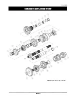
Page 10: ...PV4 118310 PAGE 8 GEARSET EXPLODED VIEW FIGURE 4 EXPLODED VIEW GEARSET...

Page 11: ...1 185 x 1 843 x 039 14 6M GBW 1 6th gear mainshaft 32T spur 15 BD 11081 1 Thrust washer splined 1 185 x 1 430 x 125 16 11082 2 Segment ring 1 102 x 1 280 x 056 17 2M GB 1 2nd gear mainshaft 21T spur...

Page 12: ...ed roller bearings 104 green 11625 GB 1 Spacer tapered roller bearings 106 blue 6 OR568M52 1 O ring pulley sprocket spacer 52mm 7 33334 GB 1 Spacer pulley sprocket 8 1302 334PP 1 Retaining ring bevele...

Page 13: ...GB 1 Shift fork 2nd gear mainshaft 4 101 GB 1 Shift fork 4 5 dog clutch mainshaft 5 35224 GB 1 Fork rod mainshaft 6 285 6 103 GB 1 Shift fork 3rd Gear countershaft 7 35222 67 1 Fork rod countershaft 4...

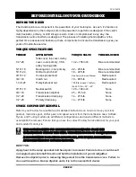
Page 14: ...5 40 9 16 18 Neutral switch 120 180 in lb None 3 4 16 Transmission dipstick 25 75 in lb None 1 2 20 Transmission drain plug 14 21 ft lb None 1 2 20 Primary drain plug 14 21 ft lb None STOCK COMPONENT...

Page 15: ...GRUDGEBOX FIGURE 7 SURGICALLY CLEAN THE LEFT SIDE OF THE TRANSMISSION CASE IN THE AREAS INDICATED ABOVE VISIT THE BAKER DRIVETRAIN YOUTUBE CHANNEL AND WATCH CLASS 4 IN THIS VIDEO WE SHOW YOU HOW TO I...

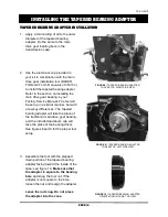
Page 16: ...but with a few key differences The tapered bearing adapter will take the place of the traditional main drive gear bearing and the included aluminum cup will take the place of the bearing driver See fi...

Page 17: ...wn in figure 14 DO NOT heat the boss from the inside of the case and keep heat away from the tapered bearing adapter that is staged and ready for installation The bearing bore boss should be heated to...

Page 18: ...bout flush with the bearing boss when the tapered bearing adapter is fully seated see figure 14 BERT TIP Do not over tighten the nut after the tapered bearing adapter is bottomed out Doing so may dama...

Page 19: ...he main drive gear apply a thin coating of transmission oil to the tapered bearing races and the main drive gear O ring see figure 17 A thicker oil could give you a false reading when checking endplay...

Page 20: ...ring followed by the remaining press tools see figure 19 INSTALLING THE MAIN DRIVE GEAR 5 With the tooling installed snug the assembly by hand while making sure the installation tool cup is properly a...

Page 21: ...measurement is between 0005 002 try spinning the main drive gear If it spins freely with no drag and no excessive noise setup is complete and you may proceed to the next step 7 Remove the tooling used...

Page 22: ...R 8 Put some transmission fluid on the outer diameter and O ring of the pulley spacer Install it onto the main drive gear with the O ring facing inward toward the bearing see figure 22 9 Put some tran...

Page 23: ...ep the active plate retracted during gearset installation into the case see figure 24 2 The time has come to stuff the gearset figure 25 into the transmission case Before that is done take time to ens...

Page 24: ...this time INSTALLING THE GEARSET 8 Put 28 32 oz transmission fluid 75 85W140 synthetic gear oil into the transmission by pouring it through the top cover cavity onto the main drive gear and shifter p...

Page 25: ...in 3rd 4th and 6th an ECM re flash is required ECM RE FLASH VALUES 1 Re install the top cover with the new gasket provided Button up the primary exhaust shift linkage and floorboards footpegs per your...

Page 26: ...PV4 118310 PAGE 24 WIRING DIAGRAM FOR IGNITION KILL SHIFT DRUMS...

Page 27: ...thin 45 days of purchase to be valid RETURNS AND EXCHANGES Any merchandise returned for any reason exchange credit or modification must be accompanied by a Returned Goods Authorization RGA number or i...

Page 28: ...10 PAGE 26 DATE ODOMETER OIL USED SERVICED BY 500 2 500 7 500 12 500 17 500 22 500 27 500 32 500 37 500 42 500 47 500 52 500 57 500 62 500 67 500 72 500 77 500 82 500 87 500 92 500 TRANSMISSION OIL CH...

Page 29: ...PV4 118310 PAGE 27 DATE ODOMETER WORK PERFORMED SERVICED BY GENERAL MAINTENANCE LOG...

Page 30: ......

Reviews: