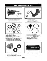
PV4-118310
PAGE 18
3. Follow the Factory Service Manual
to install the main drive gear using
BAKER TOOLA-07 or H-D
equivalent 35316C. If the H-D
equivalent tool is used, you will need
to use pulley spacer 33334-GB from
your kit for extra spacing while
pressing the tapered bearings
together.
If you need to use the pulley spacer
(33334-GB), temporarily remove the
O-ring. Remember to re-install it after
the end play is set.
4. Gently slide the assembled main drive
gear through the case. Take the loose
tapered roller bearing (HR32910J) and
slide it over the main drive gear, letter
side facing out. Slide the pulley spacer
onto the gear if needed (O-ring groove
facing bearing), followed by the
remaining press tools; see figure 19.
INSTALLING THE MAIN DRIVE GEAR
5. With the tooling installed, snug the
assembly by hand while making sure
the installation tool cup is properly
aligned and not skewed to the side of
the tapered bearing. Hold the bolt on
the inside of the case using the proper
socket and ratchet. Tighten the main
drive gear tooling on the primary side
of the bike until it is fully seated and
tight. Refer to the main drive gear tool
instructions and figure 20.
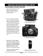
FIGURE 19 |
IF USING H-D TOOLING, THE
PULLEY SPACER IS NEEDED TO EXTEND
THE LENGTH OF THE INSTALLATION CUP
FIGURE 20 |
INSTALLING THE MAIN DRIVE GEAR
BERT TIP:
Apply pressure to the main drive
gear during this step by reaching
your left hand through the top of the
transmission case. Failure to do so
(i.e. allowing the gear to flop around)
will damage the bearing races.
Summary of Contents for GRUDGEBOX
Page 1: ...PV4 118310...
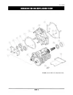
Page 8: ...PV4 118310 PAGE 6 BEARING DOOR EXPLODED VIEW FIGURE 3 EXPLODED VIEW BEARING DOOR...
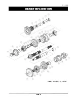
Page 10: ...PV4 118310 PAGE 8 GEARSET EXPLODED VIEW FIGURE 4 EXPLODED VIEW GEARSET...
Page 26: ...PV4 118310 PAGE 24 WIRING DIAGRAM FOR IGNITION KILL SHIFT DRUMS...
Page 29: ...PV4 118310 PAGE 27 DATE ODOMETER WORK PERFORMED SERVICED BY GENERAL MAINTENANCE LOG...
Page 30: ......


