5 | Baker Hughes
Copyright 2020 Baker Hughes Company. All rights reserved.
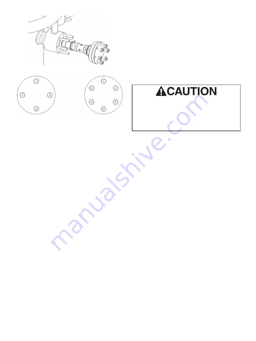
Figure 1 - Nozzle housing
Figure 2 - Bolt torquing sequences for nozzle flanges
Flushing Operations
Pipeline flushing is recommended to clean debris from the
pipeline resulting from its construction.
Water Ring Hydrostatic Testing
The hydro assembly drawing will specify whether the water ring
should require a separate hydrostatic test. DO NOT perform a
water ring hydrostatic test with the functional nozzles as expected
leakage and damage may occur to the functional nozzles. When
the blank nozzles are installed, ensure that both the inner and
outer gaskets are installed.
Downstream or Full Pipeline
Hydrostatic Testing
If the water ring is to be hydrostatically tested in conjunction with
the downstream pipe, it will be necessary at this point to remove
the blank nozzles, and reinstall the flange with a new outer
gasket and inner guide ring if required. It is important to note
that until hydrostatic testing has been fully completed; functional
spray nozzles must not be installed.
Nozzle Assembly
Desuperheating performance is reliant upon water injection of
the desuperheater spray nozzles. The nozzle must maintain
an aerosol spray effect, and a hollow cone spray pattern. Weld
slag, rust, and other debris in the water lines can disturb the
nozzle spray pattern and can result in poor water injection and
temperature control. Periodic inspection of the spray nozzle’s
water pattern should be conducted to ensure nozzle performance.
Refer to the instructions under “Inspecting Nozzle Performance”
for the detailed test procedure.
To assemble the nozzles into the desuperheater:
After inspecting the surfaces of the nozzle housing for any
damage or debris, install the nozzle gasket into the bottom of the
nozzle housing.
Securely install the nozzle holder into the nozzle housing. The
nozzle holder should fit flush with the housing surface, otherwise
remove the nozzle holder and confirm the nozzle is clean from
debris.
Install the nozzle flange gasket into the groove on the nozzle
housing.
Place the nozzle housing flange over the nozzle flange studs.
Securely tighten the nozzle flange nuts to the factory suggested
torque.
The nozzle assembly is screwed and locked in place
using a high temperature adhesive to prevent part
from coming loose due to thermal expansion caused
by the steam line. This assembly should not be
disassembled, and must be purchased as a complete
assembly.
Gaskets
Gasket seating surfaces must be free of dents, scratches,
and corrosion. Metal gasket glands should have a radial or
circular serration pattern with a surface roughness of 63 to
250 RMS. Clean mating surfaces as required and replace any
non-conforming parts. Spiral-wound gaskets must always be
replaced after disassembly.
Inspecting Nozzle Performance
Follow the disassembly instructions shown under the “Opening
Nozzle Housing” section.
1. With the nozzle holder removed from the nozzle housing,
plug the threaded holes in the side of the nozzle housing
using threaded plugs as listed in Table 2 (nozzle plug size).
2. Connect a water source to the threaded connection shown
in Table1 (lifting bolt size).
3. Apply pressure to the water line and observe the spray
pattern of the nozzle. The spray pattern should be uniform
and consistent around the perimeter of the nozzle head.
4. If nozzle spray pattern is disturbed, continue flushing
procedure with higher pressure water to determine if nozzle
can be unblocked.
5. If problem persists, contact the Baker Hughes Masoneilan
factory for a replacement nozzle assembly.
Note: The water pressure must be a minimum of 30 PSIG to
ensure the nozzle will overcome the spring coefficient and
spray properly.


