background image

The severity levels are:


l

Green


o

Vibration is below defined limits.


o

Data is collected at the configured interval.


l

Yellow


o

Vibration is between the lower and upper defined limits.


o

Acquire a dataset immediately.


o

Revert to collecting data at the configured interval.


l

Red


o

Vibration is above the upper defined limit.


o

Acquire a dataset immediately.


o

Set overall measurements to be taken at the shortest allowed interval (10 minutes).


o

Set dynamic measurements

4.7  Install and Configure System 1 Plugin

System 1 supports running a mixture of Ranger Pro devices running old and current versions of 

the firmware under specific conditions. 

Compatibility

System 1 supports Ranger Pro devices running mixed versions of firmware under these 

compatibility guidelines:

You must upgrade the System 1 Ranger Pro plugin before you upgrade device firmware. If 

you upgrade device firmware first, System 1 may decommission the installed devices. 

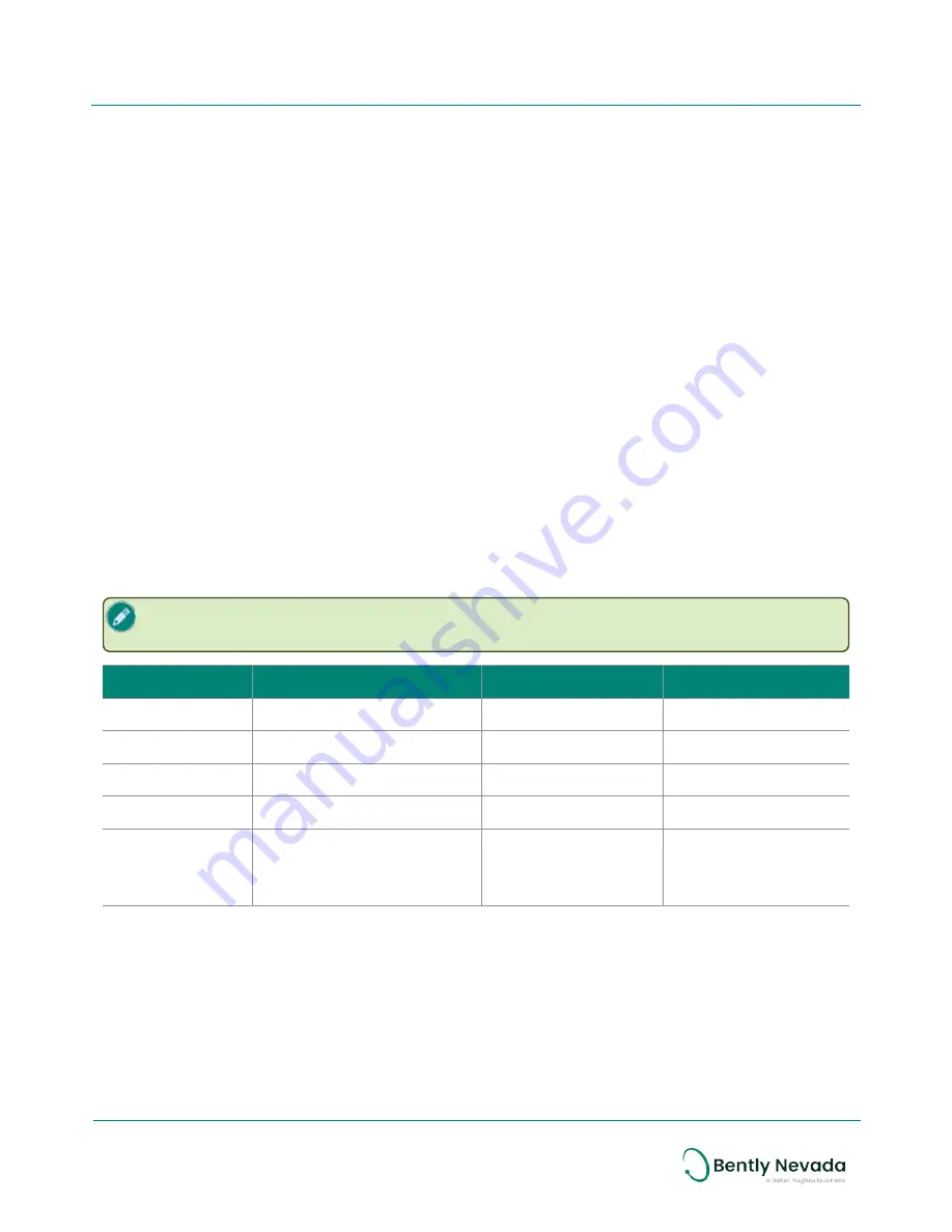
System 1 Version Ranger Pro Plugin Version

Firmware Version

Compatibility

19.1 and earlier

20XXX

2.1.2.2 (ISA100)

Yes

19.1 and earlier

20XXX

2.1.2.2 (ISA100)

Not recommended

19.2 or later

30XXX

2.1.2.2 (ISA100)

Yes

19.2 or later

20XXX

3.1.x.x (ISA100 only)

No

19.2 or later

30XXX

2.1.2.2 (ISA100)

3.1.x.x (ISA100)

3.1.x.x (WirelessHART)

Yes (recommended)

New System 1 Installation

Install System 1 and the Ranger Pro plugin before adding Ranger Pro devices as follows:

 1.  Install System 1 version 19.1 or later and appropriate hotfix and/or service packs.

 2.  Download the appropriate compatible Ranger Pro plugin from the Bently Nevada Flexera 

licensing server.

33/56

Ranger Pro Wireless Condition Monitoring Device
User Guide

125M6113 Rev. D

Summary of Contents for Bently Nevada Ranger Pro

Page 1: ...Ranger Pro Wireless Condition Monitoring Device User Guide Bently Nevada Machinery Condition Monitoring 125M6113 Rev D...

Page 2: ...s any and all liability for any direct indirect consequential or special damages claims for lost profits or third party claims arising from the use of the information whether a claim is asserted in co...

Page 3: ...and Configuration 16 4 1 Install Battery 16 4 2 Configure Network 20 4 3 Provision Devices 20 4 4 Unprovision Devices 26 4 5 Reboot the Device 28 4 6 Configure Devices 29 4 7 Install and Configure Sys...

Page 4: ...procedures The format of these markings are governed by the standards that dictate safe use and environmental compliance in a variety of regions and regulated settings More specific product safety war...

Page 5: ...use it to fail or in hazardous locations cause other unintended consequences Lithium batteries are volatile When handling and storing lithium metal batteries follow these precautions l Store and handl...

Page 6: ...amounts within the system Recycling Facilities Decommissioning of instrumentation should endeavor to minimize the impact of the waste created by disposal of system components Refer to local or regiona...

Page 7: ...Description The Ranger Pro ISA100 11a wireless sensor measures temperature acceleration and velocity Ranger Pro sensors detect acceleration using piezoelectric ceramic sensing elements in the sensor b...

Page 8: ...ou to extend the range between sensors and network access points For ISA100 networks both the tri axial and uniaxial sensors can also act as routers although using the router mode depletes the unit s...

Page 9: ...s adapters if needed l A compatible USB NFC reader Contact Bently Nevada technical support for a list of compatible readers l Ranger Pro Configuration Software 121M7997 available from Bently Nevada te...

Page 10: ...can purchase approved batteries from Bently Nevada or third party suppliers For details and ordering information see the Ranger Pro Datasheet document 125M5237 Network Requirements Ranger Pro devices...

Page 11: ...WirelessHART Network requirements Manufacturer Gateway Router Emerson Wireless 1410 1420 Gateway 4 7 84 or later N A 11 56 Ranger Pro Wireless Condition Monitoring Device User Guide 125M6113 Rev D...

Page 12: ...etwork 3 1 Consider Sensor Range A sensor can transmit data up to 150 meters 164 yards to an access point when unimpeded by environmental influences A sensor can optimally transmit data to another sen...

Page 13: ...west reasonable measurement interval to monitor vibration and temperature More frequent vibration measurements consume more power For example changing the interval from 30 to 10 minutes reduces batter...

Page 14: ...e nominal radio frequency range around the proposed location of each Ranger Pro device When connecting to a backbone router or access point the range is about 50 greater When the device is placed amon...

Page 15: ...Repeaters ought to be positioned o Relatively high above the sensors preferably at least two meters 6 feet above grade Higher placement dramatically increases signal strength o To improve radio freque...

Page 16: ...o Warning Special Conditions and Additional Information 126M6550 available from Bently com To maintain the device s IP67 dust and water resistant rating assemble the device carefully To install a batt...

Page 17: ...slight radial force and push upward until the e module is separated from the case 3 Use the battery installation tool to remove the battery retaining ring Turn the ring counter clockwise Use the magn...

Page 18: ...install and lubricate the O rings properly 5 Inspect the interior threads of the e module retaining ring to be sure they aren t damaged 6 Verify that the positive end of the battery is up and then in...

Page 19: ...e sensor in place with your finger Inspect the exterior threads of the sensor case as well as the interior threads of the e module retaining ring to be sure they are not damaged 10 Align the e module...

Page 20: ...Ranger Pro configuration software functions include l Device provisioning l Rebooting the device l Unprovisioning l Device configuration including l Applying default configurations l Saving loading an...

Page 21: ...Provision Using a USB NFC Reader on page 1 l WirelessHART gateway see Provision Using a USB NFC Reader on page 1 If a Ranger Pro device does not join the network it may be in a sleep state It periodic...

Page 22: ...ice Role as IO IO Auto or IO Router d If applicable Select the Primary Router e If applicable Select the Secondary Router 3 Click Download to apply the updated configuration to the gateway When succes...

Page 23: ...Periodic Periodic Publication period 0 zero 150 150 Stale limit Default 5 5 Retry mode Normal Normal Normal 8 For each type of Ranger Pro device verify these additional Concentrator OID 11 Read Parame...

Page 24: ...ampling Data The Sampling Data pane is displayed c Click Edit The Sampling Settings dialog box is displayed d Verify that the firmware version CF file version and OID parameters are correct for the de...

Page 25: ...Provision 8 Click Enable for 60 Minutes Wait for the unprovisioned devices to display in the Property Panel This may take five to ten minutes 9 Select the un provisioned devices and click Accept 10 I...

Page 26: ...o obtain drivers visit the website of the NFC reader vendor 4 Select the appropriate USB NFC reader in the NFC Manager tab header 5 Place the Ranger Pro device upside down on the USB NFC reader pad 6...

Page 27: ...ted and its status is changed to out of service OOS 6 In the tool bar click Provisioning Delete The Delete Devices dialog box is displayed 7 Select the device s you previously inactivated 8 Click Dele...

Page 28: ...ese steps for ISA100 devices the Ranger Pro device is unprovisioned disconnects from the network and is ready to be provisioned for the same or a new ISA100 network Although not required when changing...

Page 29: ...ng two modes Live Configuration l View modify and update sensor configurations in real time l Most often used to change device configuration on a single device Preset Configuration l View modify save...

Page 30: ...sors pane displays all devices and their status If using System 1 to modify the gateway IP address refer to the System 1 online help or user guide Configure Sensors Over the Network To configure senso...

Page 31: ...d preset configuration data 7 Select the Ranger Pro device s to which you want to apply the preset configuration To select multiple devices press CTRL or SHIFT 8 In Network Manager Sensors click Apply...

Page 32: ...ls for the new units to take effect For ranges and complete specifications see the Ranger Pro Datasheet document 125M5237 Advanced Settings After you connect to a gateway you can view device settings...

Page 33: ...nder these compatibility guidelines You must upgrade the System 1 Ranger Pro plugin before you upgrade device firmware If you upgrade device firmware first System 1 may decommission the installed devi...

Page 34: ...e Ranger Pro plugin from the Bently Nevada Flexera licensing server 7 Install the plugin 8 Open the System 1 database 9 Enable data collection 10 If needed Wait for the Configuration Out of Date messa...

Page 35: ...o use a We recommend you drill and tap a mounting hole o Verify that the machine housing is suitable for drilling a mounting hole o Refer to the machine warranty or other documentation o Consider the...

Page 36: ...chine at the mounting point o On curved surfaces use a spot facing tool to provide a flat mounting surface o Use a steel wire brush to remove all paint from the mounting surface 2 Prepare the attachme...

Page 37: ...62 in lb 6 Optional Secure the device by passing a 1mm 04 inch lanyard not provided by Bently Nevada through the fall protection hole in the base Secure the lanyard to a suitable retaining point 37 5...

Page 38: ...rk connection Dismount the device from the machine and position it closer to an access point or router l If possible improve the device s radio frequency communication by relocating it or reorienting...

Page 39: ...t be less than 50 and preferably less than 20 5 2 Validate Device Data Depending on the wireless management system you are using there are several ways to validate that each device is transmitting dat...

Page 40: ...inches s RMS X 5 Y 5 Z 5 X 1000 Y 1000 Z 1000 PeakDemod Overall Enabled N A Peak N A N A Dynamic Data Dynamic data is measured at the interval and start date time set by the user You can select the nu...

Page 41: ...r to CF file release notes for details on configuring single tri axial and repeater AIO objects Devices use firmware version 02 01 02 02 or later Byte Order Little Endian 32 bit Data type float l CH01...

Page 42: ...CC 1 SV Secondary Variable HartTag Z OVL VEL 2 TV Tertiary Variable HartTag Z PK DEMOD 3 QV Quartenary Variable HartTag X OVL ACC 4 N A HartTag X OVL VEL 5 N A HartTag X OVL ACC 6 N A HartTag X OVL VE...

Page 43: ...For details and ordering information see the Ranger Pro Datasheet document 125M5237 available from Bently com Battery Status Monitoring Battery status is updated once per hour and may be trended Batt...

Page 44: ...sits from the exterior of the sensor use an electronic contact or switch cleaner Diagnose Device Status If a device fails use the NFC reader to identify the fault The NFC reader displays additional de...

Page 45: ...legacy model Read Fault Diagnostics The sensor diagnostics data could not be read Bypass Diagnostics The sensor diagnostics data was successfully read but the model has been detected as a legacy mode...

Page 46: ...pins l Remove the battery using the battery installation tool l To clean the interior use a clean dry anti static cloth Inspect the O rings The Ranger Pro device uses two O rings to seal the unit aga...

Page 47: ...n the inside and at the bottom of the sensor module Inspect the Battery Inspect the battery before removing it Look for l Swelling deformation or elongation l Indentations or lifting of battery termin...

Page 48: ...Over the air As you upgrade the firmware monitoring may be interrupted When the firmware update is complete the Ranger Pro device restarts All nodes connected to the device are temporarily disconnect...

Page 49: ...e sensor firmware be sure you have downloaded and added current versions of the firmware to the application To update firmware using the Bently Nevada Ranger Pro ISA100 gateway 1 Verify that all Range...

Page 50: ...or Firmware dialog box is displayed 8 Do not modify TSAP and Object ID default values Click the Firmware file browse button The Open dialog box is displayed 9 Navigate to the location of the firmware...

Page 51: ...Select it and click Open The DD is listed in the dialog box 7 Click Close To update firmware using a Honeywell OneWireless Device Manager 1 Verify that all Ranger Pro devices are provisioned connected...

Page 52: ...ay hosting the sensors you want to update 4 Select the Firmware tab 5 Select a valid firmware version and click Upgrade 6 Select Network Manager Sensors tab 7 Update progress is displayed in the Firmw...

Page 53: ...vidually update the e module firmware 1 Open the Ranger Pro Configuration Software 2 Connect the NFC reader to the computer running the Ranger Pro Configuration Software 3 Place the Ranger Pro device...

Page 54: ...nrecognized The sensor identification data was successfully read but the model is not recognized Model Unsupported The sensor identification data was successfully read but the model is not supported B...

Page 55: ...e sensor firmware Update Radio Firmware Using Honeywell Gateway With one exception the process to upgrade a Ranger Pro device radio firmware on a Honeywell gateway is the same as upgrading the sensor...

Page 56: ...eaders l Verify that the latest firmware is installed on all NFC readers and device e modules and sensors l Follow your site s standards or industry s best practices for strong passwords l Only instal...

Reviews: