Bake Max TCO6G Installation And Operation Manual Download Page 8

UNPACKING 

1.  Remove all packaging and transit protection including all protective plastic coating from the exterior stainless steel panels. 

2.  Check the oven and supplied parts for damage.  Report any damage immediately to the carrier and distributor. 
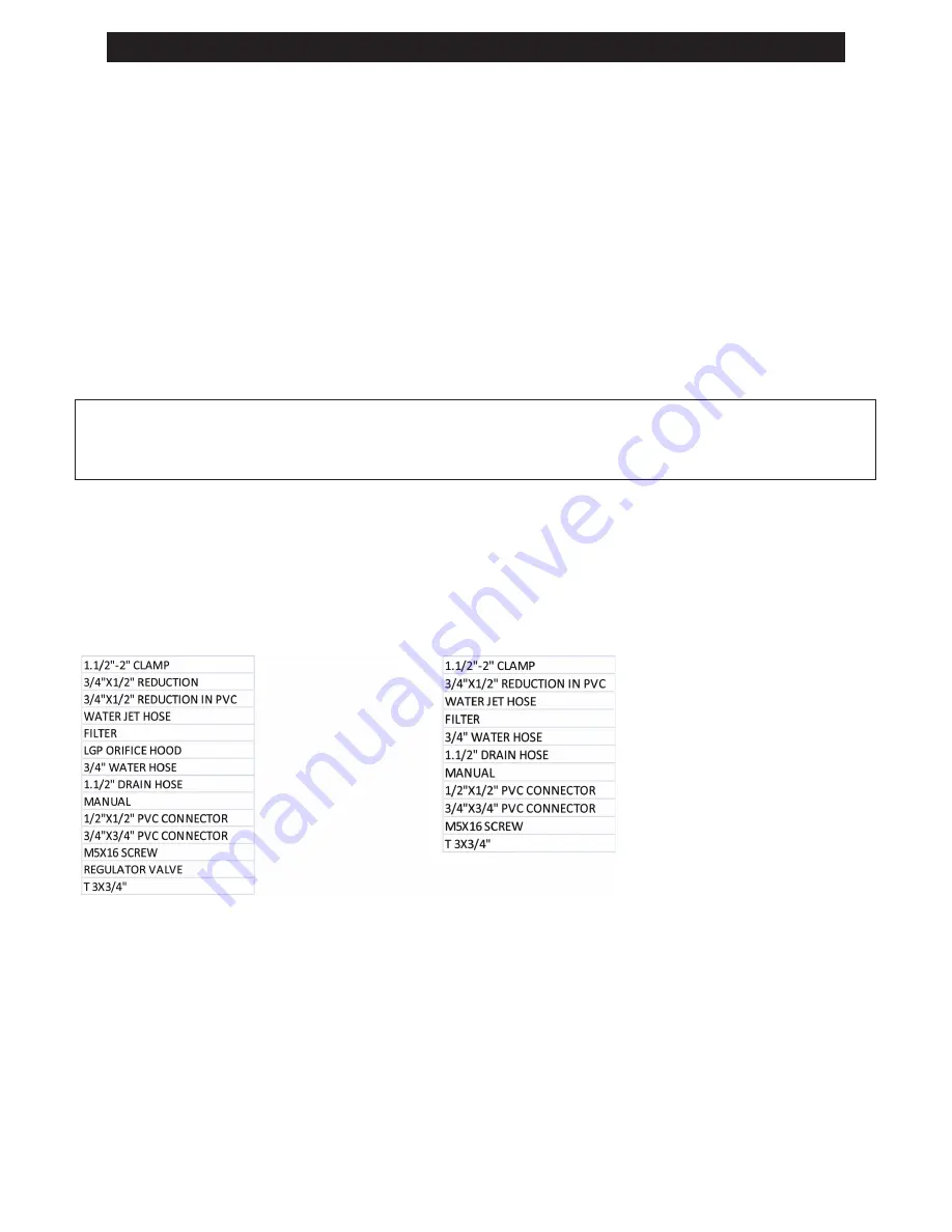
3.  Check that the following parts have been supplied with your  oven:- 

4.  Report any de ciencies to the distributor who supplied your oven. 
5.  Check that the available electrical supply is correct to that shown on the Technical Data Plate located on the front right  hand

side panel. 


LOCATION

1.  Position the oven in its approximate working position. 
2.  The unit should be positioned so that the control panel and oven shelves are easily reachable for loading and unloading. 

CLEARANCES 

To ensure correct ventilation for the motor and controls, the  following minimum installation clearances are to be adhered to: 


Top                     

8”. 20/ 0 mm 

Rear 

300mm / 12”. 

Left-hand side 

 450mm / 18”. 

Right-hand side 

 900mm / 36”. 


·

Installation shall comply with local elec

trical, health and safety requirements. 


·

It is most important that this oven is installed correctly and that oven operation is correct before use. 


·

If  you  have  any  questions  regarding  the  proper  installation  and  /  or  operation  of  this  oven,  please  contact  your  local 

distributor. 

Quali ed installation personnel are individuals, a  rm or a company which either in person or through a representative are engaged 
in and responsible for the installation of electrical wiring from the electric meter, main control box or service outlet to the electric 
appliance.

Quali ed installation personnel, licensed and bonded, must be experienced in such work, familiar with all precautions required and 
have complied with all requirements of state or local authorities having jurisdiction.

U.S. and Canadian Installations - All ovens, when installed, must be electrically grounded in accordance with local codes, or in the 
absence of codes, with the National Electrical Code ANSI/NFPA 70 - Latest Edition and/or Canadian National Electrical Code C22.2 
as applicable.

The ventilation of these ovens should be in accordance with local codes.  In absence of local codes, refer 

to the national ventilation  code titled, Standard for the Installation of Equipment for the Removal of 

Smoke and Grease Laden  Vapors  from Commercial  Cooking Equipment, NFPA-96-Latest Edition.

The appliance is to be installed with a check valve in accordance with applicable federal, province and local codes.

FCT6/7G

FCT6/7E

IMPORTANT

INSTALLATION REQUIREMENTS

Summary of Contents for TCO6G

Page 1: ...Combi Oven Touch TCO6G MODELS TCO6E TCO7G TCO7E...

Page 2: ...rating or servicing this equipment NOTICE Instructions must be posted in a prominent location that will provide the user of this equipment with procedures in the event he she smells and or detects gas...

Page 3: ...forms best please read this manual carefully and follow the instructions correctly If you have any doubts and or suggestions call Ven ncio qualified professionals will be at your disposal RECEIPT We r...

Page 4: ...y and power are in accordance with the points installed This equipment is a convertible voltage DO NOT ATTEMPT TO CHANGE THE VOLTAGE as it may be severely damaged and is not covered under warranty If...

Page 5: ...ible to touch Model TCO6G TCO7G TCO6E TCO7E TCO10G TCO12G TCO10E TCO12E No of Meals Approx 350 Approx 350 Approx 500 600 Approx 500 600 Gas 0 8 1 2 Three phase voltage V 220 380 440 220 380 440 Single...

Page 6: ...y case to connect other devices in the same socket outlet Doing so may cause overloading of the electrical installation and or poor contact Overloads can cause harmful heating to the insulation connec...

Page 7: ...er and fuse see table of circuit breakers according to the type of equipment Electric power socket outlet see power grid Socket outlet see power grid Point for drainage of water drain or sewage Refer...

Page 8: ...tions regarding the proper installation and or operation of this oven please contact your local distributor Quali ed installation personnel are individuals a rm or a company which either in person or...

Page 9: ...ENANCE SERVICE REPAIRS OR INSTALLATION Contact your dealer or the factory for your local Factory Authorized ServiceAgency The gas pressure regulator provided with the equipment must be installed when...

Page 10: ...g gas ori ces when gas pressure is applied Compounds used on threaded joints of this appliance piping must be resistant to the action of NG and LP gas and provide a gas tight seal to prevent leaks Whe...

Page 11: ...e unit during power failure Before lighting check all joints in the gas supply line for leaks Do not use an open ameto check for leaks 1 Turn pilot valves to OFF position by turning adjustment screws...

Page 12: ...pe dope on the threads of the valve DO NOT APPLY PIPE DOPE INTO ORIFICE HOOD 5 Attach the supplied propane burner ori ce hoods with a 1 2 wrench 6 Convert the pressure regulator from Natural to Propan...

Page 13: ...y other than certi ed licensed personnel will void the warranty and will result in damage to the oven and or injury to the operator To avoid burning do not use any liquid or containers loaded with pro...

Page 14: ...the turbine is for both sides in order to guarantee the best cooking only in eletric model OVEN LEVELING The oven has adjustable feet for easy leveling INSTALLATION EXAMPLE OF THE COMBI OVEN TOUCH AND...

Page 15: ......

Page 16: ...oven Eg meats potatoes Maximum capacity TCO6 30 kG 2 Pre heating It is extremely important that the oven is preheated especially for foods where the cooking time is less than 30 minutes This function...

Page 17: ...C Loin poultry etc Between 170 C to 180 C 6 Containers Grills For whole chickens grilled fried roasted and base for common baking trays Flat GNs Use up to 65mm deep to cook rice and foods in which th...

Page 18: ...Enamel Coated Stainless Steel GN 20mm high GN to fry eggs and hamburger GASTRONORM LINE ACCESSORIES GN for 06 Whole Chickens...

Page 19: ...Perforated GN 65 mm Deep perforated GN 65 mm deep Flat GN 65 mm Deep...

Page 20: ...GN to Fry French Fries Metal rgica Ven ncio manufactures all the accessories used by the Combi oven Flat Beaded Aluminum GN...

Page 21: ...ent carefully before installation and before using the device and follow all warnings Please keep this document with your device for future reference Important Use the device only in the ways describe...

Page 22: ...screen TFT graphic display and guarantees an IP65 degree of protection for agile cleaning DIMENSIONS AND INSTALLATION User Interface Dimensions The following drawing illustrates the dimensions of the...

Page 23: ...allation of the control module The following drawing illustrates the dimensions of the device s control module the dimensions are expressed in mm in The installation is planned on a flat surface with...

Page 24: ...touching the reference area Control panel fan The technical compartment fan is switched on until the operating temperature of the control module reaches the set temperature with parameter F6 and is s...

Page 25: ...escription of the washing typology There are 3 management relays dedicated to Relay K10 solenoid valve for introducing water from condenser water network Relay K11 pump with recirculating water system...

Page 26: ...our washing typologies Cycle selection and start In case a RINSEN cycle is selected and started the cycle will be immediately placed in the pre wash phase If on the other hand one of the other 3 types...

Page 27: ...temperature constant After the time has elapsed the operation of the washing system will vary according to the type of cycle defined RINSEN i e WASHING cycle Phase 2A RINSEN After the pre wash phase i...

Page 28: ...ashing cycle During the entire washing phase if enabled via parameter P3 and if the value of the Water Drain probe is higher than the maximum water flow set point 70 C the controller will activate the...

Page 29: ...p immediately If the cycle is manually stopped during phase 3B the cycle will go to phase 4B and then to phase 4B once it is completed If the cycle is otherwise manually stopped during phase 4B the cy...

Page 30: ...e with the alarm buzzer ON by informing in the controller screen PF If a power interruption occurs during a cooking cycle and the duration of the interruption is less than the time set at 240 minutes...

Page 31: ...of the cooking cycle Set point of operation during the first phase of the cooking cycle set point of operation during the preheating During the preheating the fan is turned on at full speed When the...

Page 32: ...s enabled i e if the parameter P2 is set to 1 the phase lasts until the temperature detected by the needle probe reaches the set point inside and the operating set point is an absolute value the set p...

Page 33: ...and 6 To set the phase duration operate as follows 11 Touch the option 12 Repeat steps 5 and 6 To set the set point of the inner core probe operate as follows 13 Touch the option 14 Repeat points 5 an...

Page 34: ...Setting the cooking cycle Setting the cooking type Setting the operating set point...

Page 35: ...ows 23 From any component phase the cycle 24 Touch the Finish recipe option Once the program definition is complete the controller will display a summary screen of the defined cycle Through this scree...

Page 36: ...Cycle setting screen Defined cycle summary screen...

Page 37: ...paragraph 8 2 Setting the cooking cycle to open close the vent not used in this version to switch on off the ambient light to display the value of process variables and machine status At the conclusi...

Page 38: ...Start of cooking cycle and Preheating End or interruption of the cooking cycle Extension of the cooking cycle...

Page 39: ...e operating as follows 1 Set the cooking cycle see Setting the cooking cycle 2 Touch SAVE Go to My recipes screen from where you can select the recipe to be saved 3 Touch or to go through the pages wi...

Page 40: ...Cycle summary screen to access My recipes My recipes screen Recipe replacement screen...

Page 41: ...Ensure that the device is activated and no procedure is in progress 2 Touch the recipes option 3 Touch or to select the recipe 4 Touch the display next to the recipe of interest 5 Touch The recipe wil...

Page 42: ...Access a recipe Cancellation of a recipe To cancel a recipe operate as follows 1 From point 4 Starting a recipe touch delete to cancel the reference recipe...

Page 43: ...following table shows the factory settings of the regeneration cycle inside The following table shows the factory settings of the regeneration cycle in time DEFINITION DEFAULT MINIMUM MAXIMUM Operatin...

Page 44: ...Operating set point 30 C parameter r11 0 500 C fan speed Minimum without reversing direction of travel if provided vent opening at the beginning of the cycle during the whole duration start of a speci...

Page 45: ...Access to a special cycle Start of a special cycle...

Page 46: ...Setting the cooking cycle in this case the last cycle can be started recipes from My recipes function operating cycles of the Special Cycles function Start of a preferred cycle To start a preferred cy...

Page 47: ...FUNCTION Setting the Weekly Scheduled Activation function To access the procedure operate as follows 1 Ensure that at least one recipe is stored that the device is activated and there is no procedure...

Page 48: ...set the minutes touch the display near the center touch or within 15 sec to decrease or increase the value of interest 9 Touch the option to confirm the value entered To set the recipe to start from...

Page 49: ...s set that the device is activated and there is no procedure in progress 2 Touch for 1 sec To select an activation operate as follows 3 Touch or To change an activation operate as follows 4 Repeat ste...

Page 50: ...Access to the activation procedure of the Weekly scheduled activation function Selecting an activation and activating the Weekly scheduled activation function...

Page 51: ...iables and machine status To access the procedure operate as follows 1 Ensure that the device is activated and no procedure is in progress 2 Touch 3 Touch INTERNAL VALUES Setting the language used on...

Page 52: ...and no procedure is in progress 2 Touch To select a value operate as follows 3 Touch the repeat until the green rectangle indicates the desired value To set a value operate as follows 5 Touch or to c...

Page 53: ...4 Touch or to set the password 19 5 Touch to confirm To select a parameter operate as follows 6 Touch or to select the desired parameter To set a parameter operate as follows 7 Touch the desired para...

Page 54: ...0 Needle probe offset CA3 25 50 25 50 C F 2 0 Steam reduction probe offset PARAMETER MINIMUM MAIN REGULATOR r0 1 99 C F 2 5 Operating set point differential referred to the temperature detected by th...

Page 55: ...perature detected by the ambient sensor r12 0 240 min 240 Duration of a power interruption occurring during the cooking cycle causing the interruption 3 c0 1 120 s 10 duration of the buzzer activation...

Page 56: ...n only if F0 1 2 or 3 0 SI F4 0 F5 0 Minimum fan speed included as percentage of maximum speed only if F0 3 F5 F4 100 100 Maximum fan speed included as percentage of maximum speed only if F0 3 F6 20 6...

Page 57: ...injection t6 t7 999 s 60 Cycle time for the injection of steam generated with an external humidifier t7 0 t6 s 30 Duration of steam injection generated with an external humidifier corresponding to max...

Page 58: ...ion is enabled t17 1 500 C F 2 95 Operating temperature of the boiler steam t18 1 500 C F 2 70 Boiler steam maintenance temperature t19 1 99 C F 2 2 Hysteresis by t17 t18 t20 0 240 s 2 Boiler water lo...

Page 59: ...1 normally closed active input with open contact i1 0 1 0 Fan thermal protection input type 0 normally open active input with closed contact 1 normally closed active input with open contact i2 0 1 0...

Page 60: ...MAXIMUM MEASUREMENT UNIT DEFINITION SERIAL NETWORK LA 1 247 247 Device address Lb 0 3 2 Baud rate 0 2 400 baud 1 4 800 baud 2 9 600 baud 3 19 200 baud LP 0 2 2 Parity 0 none 1 odd 2 even PARAMETER MIN...

Page 61: ...t wash Short rinse time Operating set point in the drying liquid phase Operating set point for washing preparation in tablet wash Introduction time of drying liquid Activation time of the water pump a...

Page 62: ...ngs contained in the programs To upload the settings contained in the programs operate as follows 1 Ensure that the device is deactivated and no procedure is in progress 2 Insert a USB key containing...

Page 63: ...ined in the configuration parameters To download the settings contained in the programs operate as follows 1 Ensure that the device is deactivated and no procedure is in progress 2 Insert a USB key in...

Page 64: ...meter r12 when the power is restored the cycle will be resumed from the beginning of the phase during which the interruption will have been triggered If vice versa the duration of the interruption is...

Page 65: ...a cooking cycle the cycle will be interrupted the vent will open the fan of the technical compartment will be turned on and the permanent outputs will be deactivated Micro port input alarm Resources c...

Page 66: ...oid Steam production is not started or is insufficient The oven switches itself off Fuse blown Replace fuse Alarm lack of water Tap or valve of place closed Open the valve or wait for a new supply Cha...

Page 67: ...s for the analog inputs digital inputs and analog output should be less than 10 m 32 808 ft The maximum length of user interface control module connection cables should be less than 10 m 32 808 ft Ope...

Page 68: ...1 F Protection none Digital Inputs 5 inputs 2 micro port and rotor stand end time set via the normally open normally closed configuration parameter clean contact 5 VCC 0 5 mA 3 thermal protection fan...

Page 69: ...ement 1 1A output res 250 VCA di SPST type K10 configurable for plant setting for washing water valve management 1 1A output res 250 VCA di SPST type K11 configurable for plant setting for washing liq...

Page 70: ......

Page 71: ...P FLANGE ALL 8 02 13 00000167 22 LAMP GLASS ALL 2 80 09 00020155 23 LAMP SILICON SEAL ALL 2 80 60 03000528 24 LAMP ALL 2 80 26 00056422 25 LAMP SOCKET 12V 50W ALL 4 02 12 00000008 26 NOZZLE BODY NUT A...

Page 72: ...02 13 12002500 TCO 6 7 8 02 13 07005100 TCO 10 12 8 02 13 12002600 49 EXTERNAL CHUTE ALL 8 02 13 00003800 50 FRONTAL OUTER LOWER CLOSING ALL 8 02 13 07000031 TCO 6 7 GAS TCO 10 12 GAS TCO 6 7 ELET TC...

Page 73: ...T CZ ALL 4 02 12 00006121 6 BTWP TERMINAL 6 10T VD AM ALL 4 02 12 00006119 7 GAS WIRING TCOG 2 80 11 07001222 8 COMPENSATOR ALL 3 97 01 10000889 9 CONTACTOR BREAKER FIXING RAIL ALL 4 02 08 00004454 10...

Page 74: ...TCO 10 12 2 90 03 00150817 TCO 6 7 8 02 13 07000080 TCO 10 12 8 02 13 12000044 3 TOUCH SCREEN BOARD 338L ALL 2 80 11 00020671 4 SENSOR SUPPORT ALL 8 02 13 07000082 5 MAGNETIC SWITCH ALL 2 80 25 000230...

Page 75: ...8160 ORIFICE HOOD N 56 LPG 8 27 05 02588115 TCO 6 7 8 02 13 07006400 TCO 10 12 8 02 13 12002900 7 MANIFOLD FASTENER ALL 8 02 13 07000085 8 UNIVERSAL IGNITOR ALL 4 02 12 00050842 9 FLAME SENSOR ALL 2 8...

Page 76: ...UPPORT RUBBER ALL 2 80 60 00006049 TCO 6 7 8 02 13 07006600 TCO 10 12 8 02 13 12002200 6 HANDLE ALL 8 97 01 84179000 7 BESEL ALL 8 02 13 00000241 8 INNER GLASS LOCK ALL 8 02 13 03010014 9 DOOR SHUTE O...

Page 77: ...ALL 4 02 12 00006119 7 COMPENSATOR ALL 3 97 01 10000889 8 THREE PHASE WIRING 240V TRIF 240V 2 80 11 07013222 9 CONTACTOR BREAKER FIXING RAIL ALL 4 02 08 00004454 10 WIRE PASS ALL 2 80 57 01000173 TCO...

Page 78: ...1 2 4 3 5 6 7 8 9 12 23 11 19 22 19 24 9 9 13 15 14 17 15 18 16 20 20 10 12 6 21 6 25 26 27 28 29 31 30...

Page 79: ...80 60 03000531 13 SMALLER BOX ASSY ALL 8 02 13 00002900 14 HOSE 1 1 2 ALL 2 80 27 01000288 15 CLAMP 14 32 44 ALL 2 80 01 09020805 16 SMALLER BOX ASSY ALL 8 02 13 00002800 17 HOSE 1 1 4 ALL 2 80 27 01...

Page 80: ......

Page 81: ...7000057 19 WATER PRESSURE REGULATOR ALL 4 02 12 05170681 20 HOSE 10x4 2x1250mm ALL 2 80 27 37015010 21 CONNECTOR 1 2 NPT x 5 8 NPS ALL 8 02 13 00000254 22 SMALL BOX ASSY ALL 8 02 13 00002900 23 HOSE 3...

Page 82: ...y inversor 12V input Interface Module Standard not applied ground wire USB port Control Module RS 485 MODBUS input breaker Washing Water injection Safety Thermal Switch motor protection Reserved Drain...

Page 83: ...4 13 12 11 10 09 08 07 M INV1 Frequency Inverter A12 GND GND D14 D15 D16 A0 D0 R13 R14 R24 4 5 13 14 15 16 18 20 22 26 1 2 3 6 8 9 10 25 24 10V AI1 GND 24V GND DI1 DI2 DI3 A B R2 R22 07 Common 08 PTC...

Page 84: ...eam out then open the entire door Do not spray water from the spray head on the door glass or lights unless the temperature is below 90 C The glass can break Every time before starting the device make...

Page 85: ...after manual cleaning to wash cleaning products Failure to do so may result in damage to the surface of the cooking chamber and its discoloration during the following use at high temperatures Such dam...

Page 86: ...e leads and the heating elements After cleaning the cooking chamber of the device start cleaning Under no circumstances should the temperature exceed 70 C Repeat the process if necessary Rinse the doo...

Page 87: ...tenance instructions helps to significantly extend the life of the device and ensures its smooth operation Annual Maintenance Perform quarterly maintenance It is also necessary to check the installati...

Page 88: ...y 12 months of operation This verification must be carried out by the technicians of a service company authorized by BAKEMAX The customer is required to produce a record of such service events Strict...

Page 89: ...glass light bulbs resistors contactors fuses relays solenoids digital controllersandthermostats arenotcoveredbythiswarranty In the case of its electric motors being manufactured by a third party when...

Page 90: ...______________________ State ______________ _____________________________________ Signature Buyer Cut out 2nd COP OF THE BUYER COMPLETE ALL FIELDS WITH A LEGIBLE CAPITAL LETTER Owner _________________...

Page 91: ......

Page 92: ...170 Millennium Blvd Moncton NB E1E2G8 3601 Pinnacle Point Dr Dallas TX 75211 Toll Free 1 800 565 BAKE 2253 Telephone 1 506 858 8990 Fax 1 506 859 6929 E mail sales bakemax com Web site www bakemax com...

Reviews: