Troubleshooting
82
Electrical Control System
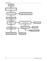
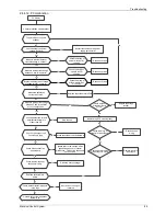
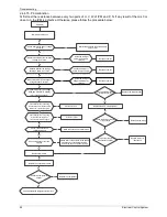
2.4.4.6. E4 malfunction
Judge 1: Outdoor condenser temp. sensor (T3) is malfunction
Judge 1: Outdoor condenser temp. sensor (T3) is malfunction
E4 display
E4 display
No
No
Replace condenser temp. sensor(T3)
Replace condenser temp. sensor(T3)
Check whether the wiring of the
condenser temp. sensor(T3) is
broken off
Check whether the wiring of the
condenser temp. sensor(T3) is
broken off
Check whether the resistance of
condenser temp. sensorT3) is wrong
refer to the
Appendix
1
Check whether the resistance of
condenser temp. sensorT3) is wrong
refer to the
Appendix
1
Yes
Connect the wiring well
Connect the wiring well
Yes
Judge 2: Outdoor ambient temp. sensor (T4) is malfunction
Judge 2: Outdoor ambient temp. sensor (T4) is malfunction
No
Replace outdoor ambient
temperature sensor (T4)
Replace outdoor ambient
temperature sensor (T4)
Check whether the wiring of the
outdoor ambient temperature
sensor (T4) is broken off
Check whether the wiring of the
outdoor ambient temperature
sensor (T4) is broken off
Check whether the resistance of
outdoor ambient temperature
sensor (T4) is wrong refer to the
Appendix
1
Check whether the resistance of
outdoor ambient temperature
sensor (T4) is wrong refer to the
Appendix
1
Yes
Connect the wiring well
Connect the wiring well
Yes
Judge 3: Compressor discharge temp. sensor (T5) is malfunction
Judge 3: Compressor discharge temp. sensor (T5) is malfunction
No
Replace compressor discharge
temperature sensor (T5)
Replace compressor discharge
temperature sensor (T5)
Check whether the wiring of the
compressor discharge temperature
sensor (T5) is broken off
Check whether the wiring of the
compressor discharge temperature
sensor (T5) is broken off
Check whether the resistance of
compressor discharge temp. sensor
(T5) is wrong refer to the
Appendix
2
Check whether the resistance of
compressor discharge temp. sensor
(T5) is wrong refer to the
Appendix
2
Yes
Connect the wiring well
Connect the wiring well
Yes
No
Replace outdoor main PCB
Replace outdoor main PCB
No
Summary of Contents for BSBSI36CTM
Page 5: ...External Appearance General Information 3 2 External Appearance 2 1 Indoor Units Duct ...
Page 15: ...Wiring Diagrams 13 4 Wiring Diagrams BSBSIE36CTM BSBSIE48CTM BSBSIE60CTM ...
Page 22: ...Field Wiring 20 Duct Type 10 Field Wiring ...
Page 25: ...Dimensions 23 Outdoor Units Model Unit mm W D H W1 A B BSBSIC60CTM 952 415 1333 1045 634 404 ...
Page 28: ...Wiring Diagrams 28 Outdoor Units 4 Wiring Diagrams BSBSIC36CTM BSBSI48CTM BSBSIC60CTM ...
Page 42: ...Installation Installation 43 ...
Page 82: ...Troubleshooting Electrical Control System 85 ...


