107
Chapter 4
CARAVAN EQUIPMENT
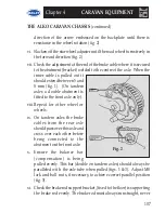
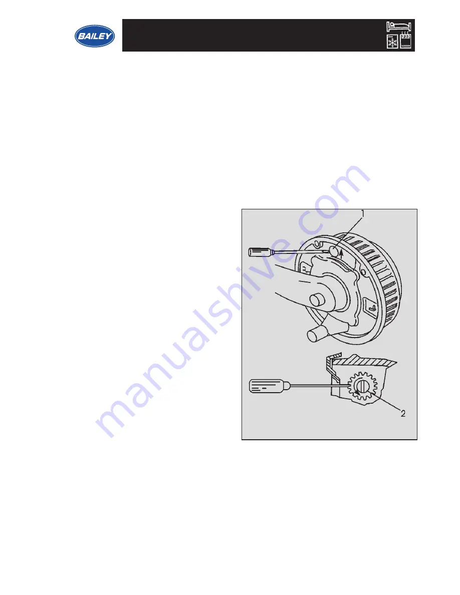
direction of the arrow embossed on the backplate until there is
resistance in the wheel rotation (fig. 2).
vi. Slacken off the starwheel adjuster until the road wheel turns freely in
the forward direction (fig. 2).
vii. Check the adjustment at the end of the brake cable where it is secured
to the abutment (bracket) welded to the centre of the axle. When the
inner cable is pulled out it
should extend between 5 and
8 mm (fig. 1). (On tandem
axles a double abutment is
fitted to the front axle only).
viii. Repeat for other wheel or
wheels.
ix. On tandem axles the brake
cables from the rear axle
should pass over this axle and
cross over each other before
being connected to the
abutment on the front axle.
x
.
Ensure the balance bar
(compensation) is being
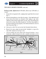
pulled evenly. This bar (double on tandem axles) should always be
paralleled with the axle tube when pulled (figs. 1 & 3). Adjust M8
lock and ball nuts, if necessary, to achieve correct parallel position
(fig. 3).
xi. Check the brake rod support bracket, (fixed to the floor) is supporting
the brake rod evenly. The brake rod must always run straight, never
Fig. 2
THE ALKO CARAVAN CHASSIS
(continued)
Summary of Contents for 2002 Series
Page 1: ...Bailey of Bristol 2002 Series Owners Manual...
Page 2: ......
Page 15: ...9 Chapter 2 CARAVAN TOW VEHICLE MAYBE NO YES EQUAL 85...
Page 52: ...46 Chapter 3 CARAVAN SERVICE SYSTEMS...
Page 57: ...51 Chapter 3 CARAVAN SERVICE SYSTEMS CONTROL PANEL SPB2...
Page 135: ...129 Chapter 5 GENERAL ASSEMBLING THE BUNKS 2 1 5 4 3 6...
Page 146: ...140 Chapter 6 TECHNICAL INFORMATION 230 VOLT 12 VOLT PRIMARY CIRCUIT DIAGRAM RANGER...
Page 147: ...141 Chapter 6 TECHNICAL INFORMATION 230 VOLT 12 VOLT PRIMARY CIRCUIT DIAGRAM SENATOR...
Page 160: ...154 Chapter 6 TECHNICAL INFORMATION NOTES...
Page 161: ...155 Chapter 6 TECHNICAL INFORMATION NOTES...
Page 163: ......
Page 164: ...Bailey of Bristol South Liberty Lane Bristol BS3 2SS England www bailey caravans co uk...


