


22
22
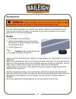
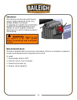
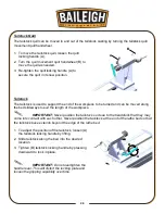
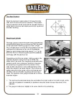
Tool Rest
Position the tool rest as close to the workpiece as
possible. It should be
1/8” (3mm) above the
centerline of the workpiece.
1. Turn off and unplug the lathe from the power
source.
2. Position the tool rest carriage on the bed by
releasing the carriage handle and sliding base
to the desired position. Tighten the carriage
handle to hold the position of the tool rest
carriage.
3. Adjust the height of the tool rest by loosening
the locking handle and raising or lowering tool rest.
IMPORTANT: Should adjustment of the tool rest clamping device become
necessary, turn “OFF” the machine, reach under the bed, and adjust the clamping nut.
Note: The locking handle is adjustable. Simple pull up on the handle, rotate it on
the pin and then release. Make sure the lock handle seats itself properly upon the pin.
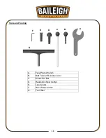
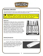
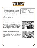
Face Plate
IMPORTANT: To reduce the risk of injury, when using the included 3" (76 mm)
faceplate (A), do not mount pieces larger than 6" (152 mm) in diameter and up to 6" (152 mm) in
length. For mounting larger pieces, be sure to use an appropriately sized faceplate.
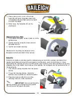
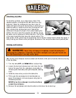
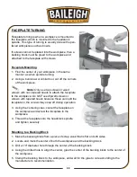
Removing Face Plate
1. Turn off and unplug the lathe from the power
source.
2. Use the 3 mm hex wrench (A) to unlock the
set screws (B) at least two full turns.
A
B
A
B
Summary of Contents for WL-1218VS
Page 41: ...38 38 WIRING DIAGRAM ...
Page 42: ...39 39 LATHE PARTS DIAGRAM ...
Page 49: ...46 46 NOTES ...
Page 50: ...47 47 NOTES ...
Page 51: ...48 48 NOTES ...