24
24
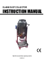
REMOTE RESET AND CLEAR FUNCTION
Clear
1. Press the reset button (A) on the control box for 3 seconds until the receiver “beep” 3 times.
Reset
2. Press the reset button (A) on the control box for 1 second until the receiver “beep” once.
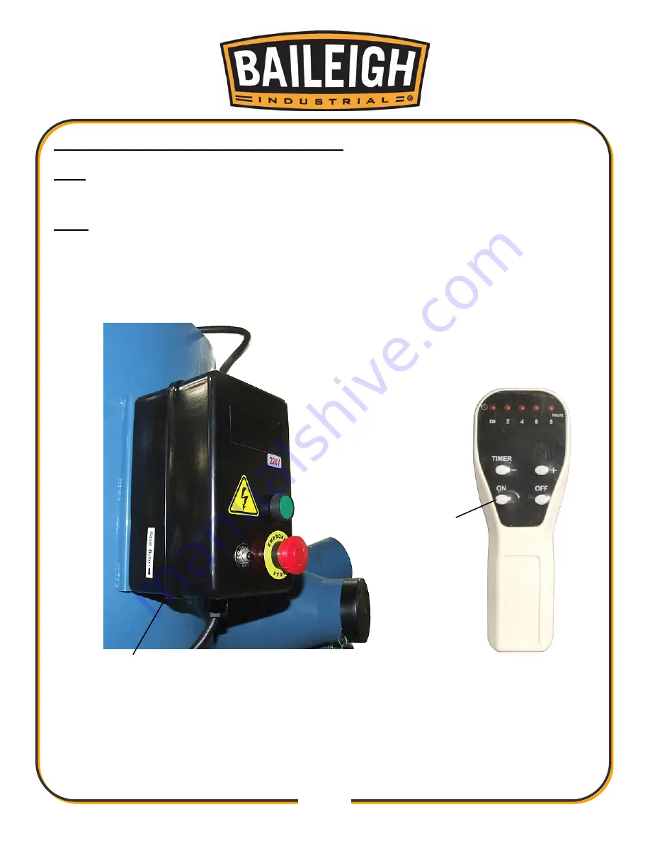
3. Press “ON” button (B) on the hand held remote control until the receiver “beep” twice. If
using more than one remote, repeat this step for all remotes before continuing.
4. Press the reset button (A) on the control box for 3 seconds until the receiver “beep” 3 times.
A
B
Summary of Contents for DC-6000C
Page 15: ...13 13 CONTENTS OF PACKAGE ...