background image


SAVE THESE INSTRUCTIONS. 

Refer to them often and use them to instruct others. 
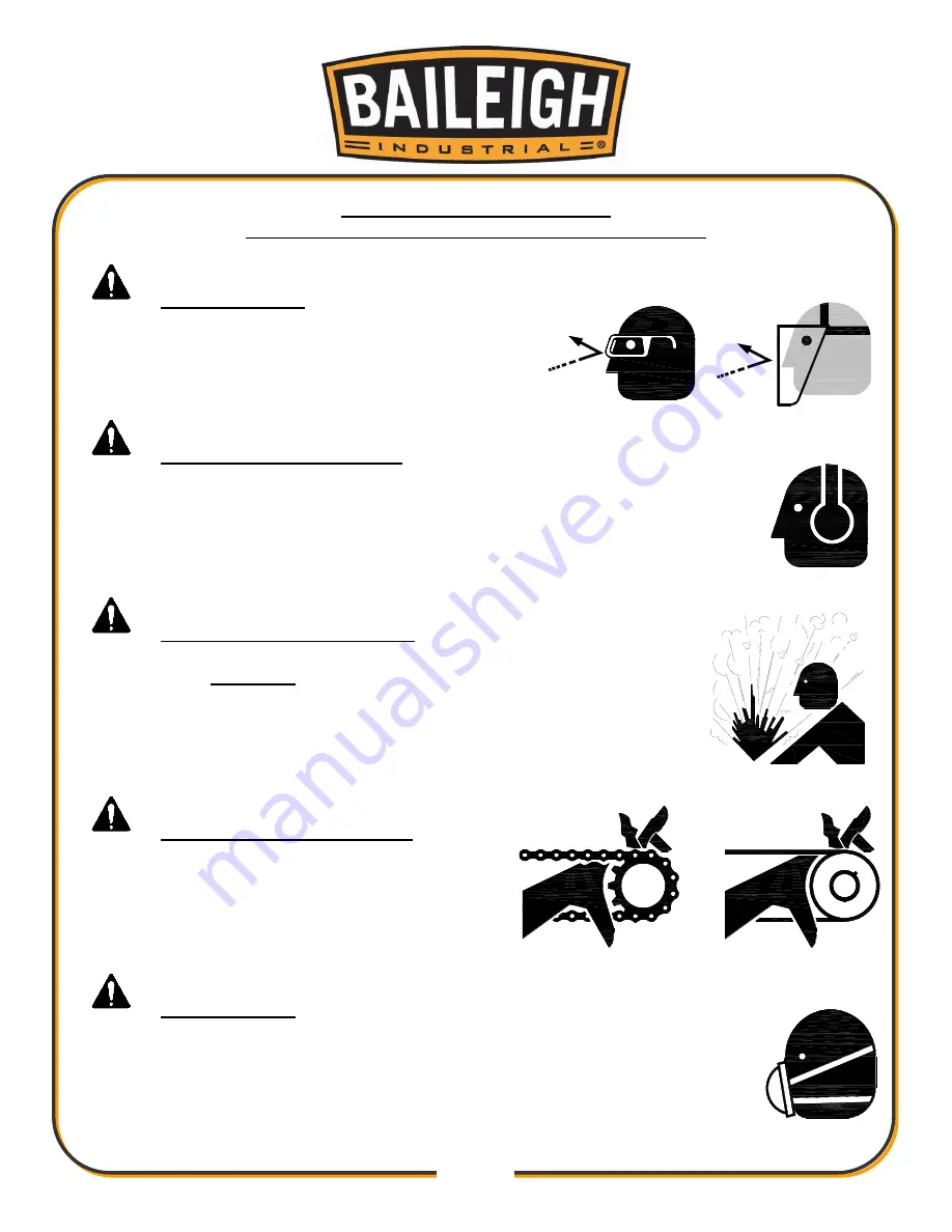
 

PROTECT EYES 


Wear safety glasses or suitable eye protection 
when working on or around machinery. 


PROTECT AGAINST NOISE 


Prolonged exposure to loud noise can cause impairment or loss of 
hearing. Wear suitable hearing protective devices such as ear muffs or 
earplugs to protect against objectionable or uncomfortable loud noises. 


HYDRAULIC HOSE FAILURE 


Exercise 

CAUTION

 around hydraulic hoses in case of a hose or 

fitting failure. 


BEWARE OF PINCH POINTS 


Keep hands and fingers clear of all potential 
pinch points. These include sprockets and 
chains along with belts and pulleys. 


DUST HAZARD 


Wear appropriate dust mask. Dust created while using machinery can 
cause cancer, birth defects, and long term respiratory damage. Be aware 
of the dust hazards associated with all types of materials. 


Summary of Contents for BSVT-18P

Page 1: ...LDINGS LLC IS PROHIBITED Baileigh Industrial Holdings LLC Inc does not assume and hereby disclaims any liability for any damage or loss caused by an omission or error in this Operator s Manual resulti...

Page 2: ...LECTRICAL 21 MACHINE SETUP AND ADJUSTMENTS 23 Blade Changing 23 Blade Tracking Adjustment 24 Saw Bow Tilt Adjustment 25 Vise plate positioning 25 Feeding Stroke 27 Blade Speed Adjustment 28 Feed Force...

Page 3: ...ON AND MAINTENANCE 45 Lubrication 46 Hydraulic Oil System 46 Oil Disposal 46 Accessing and Cleaning the Coolant System 46 Oils for Lubricating Coolant 46 Pneumatic Care 46 Bow Tilt Tension Adjustment...

Page 4: ...n notice to Seller of any suspected defect in the Goods prior to the expiration of the warranty period The original end user must also obtain a RGA from Seller prior to returning any Goods to Seller f...

Page 5: ...emedies provided under this Agreement or at law or equity Attorney s Fees In the event legal action is necessary to recover monies due from Buyer or to enforce any provision of this Agreement Buyer sh...

Page 6: ...Description of the functional parts of the machine Capacity charts Setup and start up instructions Machine operation Scheduled maintenance Parts lists GENERAL NOTES After receiving your equipment remo...

Page 7: ...zardous situation which if not avoided will result in death or serious injury WARNING Indicates a hazardous situation which if not avoided could result in death or serious injury CAUTION Indicates a h...

Page 8: ...s or earplugs to protect against objectionable or uncomfortable loud noises HYDRAULIC HOSE FAILURE Exercise CAUTION around hydraulic hoses in case of a hose or fitting failure BEWARE OF PINCH POINTS K...

Page 9: ...HIGH VOLTAGE USE CAUTION IN HIGH VOLTAGE AREAS DO NOT assume the power to be off FOLLOW PROPER LOCKOUT PROCEDURES EMERGENCY STOP BUTTON In the event of incorrect operation or dangerous conditions the...

Page 10: ...making any modifications or alterations to a Baileigh machine Modifications or alterations to a machine may pose a substantial risk of injury to the operator or others and may do substantial damage to...

Page 11: ...may affect proper machine operation 15 Observe work area conditions DO NOT use machines or power tools in damp or wet locations Do not expose to rain Keep work area well lighted DO NOT use electricall...

Page 12: ...Blade Feed Operation Pneumatic over Hydraulic Blade Feed Air Supply 0 5 1 0CFM 80 100psi 55 69MPa Pneumatic Feed Force 0 150lbs 0 68kgs Vise High x Open max 6 152mm x 18 457mm Table Height 39 5 1003mm...

Page 13: ...des For specific application needs or future machine purchases contact the Sales Department at sales baileigh com Phone 920 684 4990 or Fax 920 684 3944 Note The photos and illustrations used in this...

Page 14: ...age painted surfaces Follow manufacturer s label instructions when using any type of cleaning product After cleaning wipe unpainted metal surfaces with a light coating of quality oil or grease for pro...

Page 15: ...t there are no cables or pipes in the area of the forks Move the machine to the required position and lower gently to the floor Level the machine so that all the supporting feet are taking the weight...

Page 16: ...s If long lengths of material are to be fed into the machine make sure that they will not extend into any aisles LEVELING The machine should be sited on a level concrete floor Provisions for securing...

Page 17: ...e pump After installation of the machine and before machine startup bring the oil level up to 90 of capacity Refer to any labels or marking affixed to the outside of the machine If none exist use SAE...

Page 18: ...15 15 OVERALL DIMENSIONS...

Page 19: ...16 16...

Page 20: ...hex head bolts Manual Feed Handwheel 1 Remove the tape securing the key to the shaft and install the handwheel onto the shaft over the key 2 Secure the handwheel to the shaft by tightening the set sc...

Page 21: ...rom 0 5 1 0CFM 80 100psi 55 69MPa supply air to the air filter through the 1 4 NPT inlet port 2 Drain any accumulate moisture within the filter at least monthly Coolant Filling 1 Fill the saw base wit...

Page 22: ...19 19 GETTING TO KNOW YOUR MACHINE A B C D F E I H G J K L M O P Q R S N...

Page 23: ...stop coolant flow H Light Switch Turn work light on and off I Start Button Press to start band saw blade J Stop Button Press to stop band saw blade K Power Indicator Light Illuminates whenever main m...

Page 24: ...n low voltage will damage the motor In the event of a malfunction or breakdown grounding provides a path of least resistance for electric current to reduce the risk of electric shock This machine is e...

Page 25: ...iately Power cord connection 1 Turn the main disconnect switch on the control panel to the OFF position 2 Unwrap the power cord and route the cord away from the machine toward the power supply a Route...

Page 26: ...E 2 Carefully remove the blade through the large opening in the saw table 3 Using compressed air blow out metal chips and grit from between the bearings blade guides and inside of the blade guards an...

Page 27: ...to see if the back edge of the blade has maintained an approximate 1 32 gap from the flange on the back of blade wheels If the blade rides against the flange or is more than 1 32 away from the flange...

Page 28: ...s can be mounted to the saw table 1 Place the rear vise plate 15 in a position on the table so the hold down bolts 14 are aligned with two of the eight threaded mounting holes in the tabletop 2 Use a...

Page 29: ...wheel may be attached to either vise plate It is recommended that the angled edge of the plate be used when performing miter cuts and the vertical edge used when making vertical cuts in order to clam...

Page 30: ...de exits a cut To adjust 1 Manually feed the saw bow forward to a position in which the teeth of the saw blade are at least 1 4 6 3mm past the farthest thickness of the material to be cut 2 Hold the s...

Page 31: ...bronze Medium carbon steel 180 210 5 to 12 50 100 Low carbon steel 245 275 Aluminum Copper Brass 255 285 Over 12 80 and over 3 Push the start button on the control panel Twist the blade speed control...

Page 32: ...ce part and the upper pulley housing to protect the operator from the exposed blade Second it positions the upper blade guides close to the piece part for support of the blade To properly position the...

Page 33: ...de has been properly tensioned 3 Loosen the lock nut A while holding the adjuster B 4 Turn the adjuster to set the bearing to just barely touch the blade 0 003 This clearance can be measured with a pi...

Page 34: ...the cut off piece can move sideways after it is cut off Otherwise it could get wedged against the blade and thrown violently Never turn the saw ON before clearing everything except the work piece ben...

Page 35: ...s approximately 300cm of the material should be cut for breaking in If large work piece dimensions are to be cut we recommend a breaking in period of about 15 minutes After breaking in you may slowly...

Page 36: ...easured from gullet to gullet G GAUGE The thickness of the blade H TOOTH SET The distance a tooth is bent from the blade I KERF The width of material that is removed by the blade when cutting Width of...

Page 37: ...for transversal or inclined cutting of solid small and average cross sections or pipes in laminated mild steel and gray iron or general metal POSITIVE RAKE TOOTH 9 10 positive rake and constant pitch...

Page 38: ...l use for materials with dimensions superior to 5 mm Used for the cutting of steel castings and hard nonferrous materials WAVY SET Set in smooth waves This set is associated with very fine teeth and i...

Page 39: ...G A SAW BLADE A general purpose blade is furnished with this band saw To achieve a quality economical and efficient saw cut the following points must be taken into consideration Type of material being...

Page 40: ...37 37...

Page 41: ...ides Forcing a large width blade to cut a small radius Using a blade with an improperly finished weld joint Allowing the blade to run when not in use NEVER leave an unattended blade running MATERIAL S...

Page 42: ...turn off the machines when the work is completed Disconnect power before adjusting servicing or changing blade Inspect damaged parts Before further use of bandsaw guards or other parts that are damag...

Page 43: ...is aligned with the blade Replace blade brush if worn Inspect the blade replace if worn or if missing teeth Check that the proper blade is installed Check the blade tension adjust if needed Visually...

Page 44: ...essure chart 14 Press the STOP button to stop the bow movement if needed a The saw bow will advance until the forward stop limit switch is engaged Then the saw blade will stop the frame will retract t...

Page 45: ...ve metal chips to buildup in the pan The chips may be carried back into the saw causing premature wearing of the blade blade guides and blade wheels Clean the cutting fluid tray as often as needed Cla...

Page 46: ...it is science There are so many variables that it is virtually impossible to cover even most of the possible combinations of factors However in general you want to cut according to the cutting rage i...

Page 47: ...de manufacturer you need not make any adjustments for subsequent cuts from that same material If you are cutting too slowly according to that recommendation gradually increase the feed rate over the n...

Page 48: ...ricant to all non painted surfaces Thoroughly clean the machine to remove shavings especially from the coolant tank Removal of pump from its housing cleaning of the suction filter and suction zone Cle...

Page 49: ...per manner following your local regulations Accessing and Cleaning the Coolant System Clean the drain screens on the machine base and the drains on the ends of the table Drain and wash out the dirt an...

Page 50: ...the M12 x 90L bolt will lessen the tension of the springs This will allow the bow to tilt more easily but may be harder to hold in position 3 Tightening the M12 x 90L bolt will increase the tension of...

Page 51: ...48 48 ELECTRICAL DIAGRAM...

Page 52: ...49 49 PNUEMATIC HYDRAULIC DIAGRAM...

Page 53: ...50 50 NOTES...

Page 54: ...51 51 NOTES...

Page 55: ...52 52 NOTES...

Page 56: ...TOWOC WI 54220 PHONE 920 684 4990 FAX 920 684 3944 www baileigh com BAILEIGH INDUSTRIAL HOLDINGS LTD UNIT D SWIFT POINT SWIFT VALLEY INDUSTRIAL ESTATE RUGBY WEST MIDLANDS CV21 1QH UNITED KINGDOM PHONE...

Reviews: